Method for ascertaining topography deviations of a dressing tool in a grinding machine

a technology of a dressing tool and a grinding machine, which is applied in the direction of gear teeth, gear teeth, gear-teeth manufacturing apparatus, etc., can solve the problems of inability to accurately ascertain the actual geometry of a grinding tool, large time expenditure, and inability to accurately measure the dressing disc, etc., to improve the automation improve the accuracy of the dressing process, and improve the effect of machine capacity utilization

Active Publication Date: 2016-09-13
KLINGELNBERG AG
View PDF3 Cites 0 Cited by
  • Summary
  • Abstract
  • Description
  • Claims
  • Application Information

AI Technical Summary

Benefits of technology

[0036]Due to the use of the invention, grinding machines become more cost-effective and the machining can even be performed more precisely than heretofore under certain circumstances.
[0038]The invention allows optimized utilization of the machine capacity, an improvement of the automation of the dressing process, and repeatable, ultrahigh accuracies with a low proportion of rejects.
[0039]The invention allows the replacement intervals of the dressing roller to be lengthened and excessively frequent replacement of the dressing roller to be prevented. A higher profile consistency is achieved by the use of the invention, with elevated, i.e., lengthened service life of the dressing roller.
[0040]A method of the invention allows the dressing movement of the dressing tool, which is predefined (programmed) in the machine, to be adapted, so that in spite of a dressing tool which is worn to a certain degree, it can still be used for dressing the grinding tool. In this way, the replacement interval of the dressing tool can be optimized.

Problems solved by technology

Experiments indicate that such a coordinate scanning sensor does not appear to be suitable for measuring the dressing disc 20, or for measuring the grinding tool 1, however.
Therefore, it is only possible with great time expenditure to ascertain the actual geometry of a grinding tool 10.
In addition, such a topography measurement has inaccuracies because of the graininess of the grinding tool 10.

Method used


Image

  • Method for ascertaining topography deviations of a dressing tool in a grinding machine
  • Method for ascertaining topography deviations of a dressing tool in a grinding machine
  • Method for ascertaining topography deviations of a dressing tool in a grinding machine

Examples


Embodiment Construction

[0056]Terms are used in conjunction with the present description which are also used in relevant publications and patents. However, it is to be noted that the use of these terms is only to serve for better understanding. The ideas of the invention and the scope of protection of the patent claims are not to be restricted in the interpretation thereof by the specific selection of the terms. The invention may readily be transferred to other term systems and / or technical fields. The terms are to be applied accordingly in other technical fields.

[0057]All figures are schematic and are not to scale.

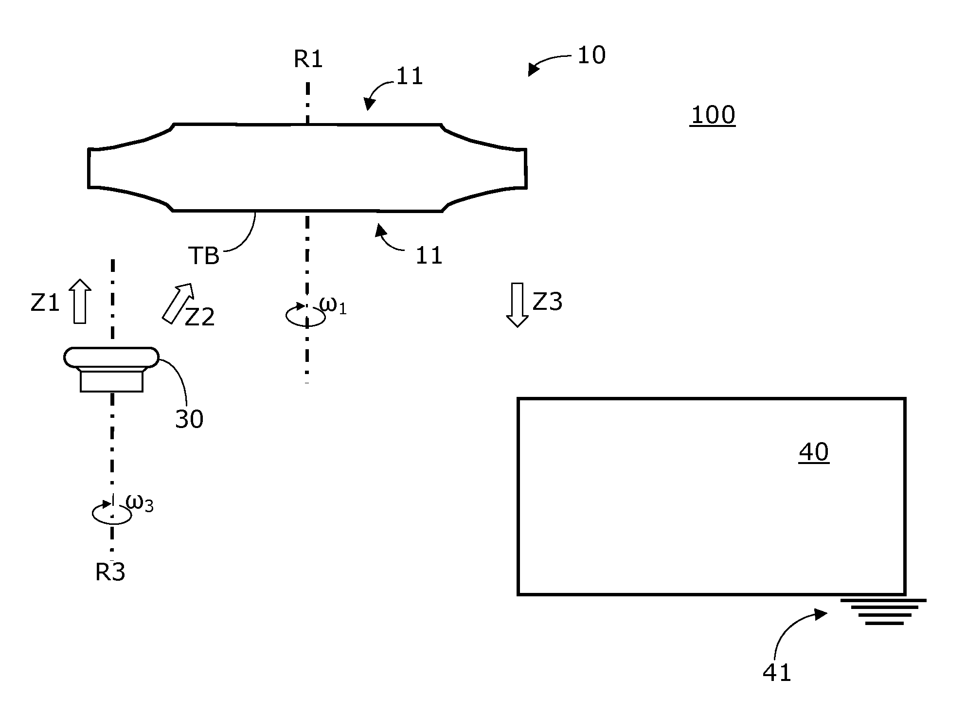
[0058]The principle of the invention will be described hereafter on the basis of the greatly simplified schematic illustration of FIG. 4. FIG. 4 only shows the essential elements of a grinding machine 100 and the fundamental (relative) movements of these elements.

[0059]A side view of a (profile) grinding disc 10 can be seen, which can be rotationally driven about a tool axis R1. The rotational m...


PUM


Abstract

The invention relates to a method for ascertaining topography deviations of a dressing tool. The method includes executing a predefined relative movement of a dressing tool in relation to a dressable grinding tool, wherein during the execution of the relative movement, at least one contour region of the dressing tool is transferred into a transfer region of the grinding tool. A plunging body made of material which can be ground in the machine is provided. The transfer region of the grinding tool is moved into the vicinity of the plunging body by a relative infeed movement. A rotational movement of the grinding tool around an axis of rotation is executed. Plunging the transfer region of the grinding tool into the material of the plunging body, to thus perform a transfer of the topography of the transfer region into an imaging region of the plunging body. A scanning movement of the topography is performed of the plunging body using a coordinate scanning sensor and a computational ascertainment by means of a computer of at least one item of coordinate information, which permits a statement about the actual geometry of the dressing tool.

Description

CROSS-REFERENCE TO RELATED APPLICATIONS[0001]This application claims priority under 35 U.S.C. §119(a)-(d) to European Patent Application No. EP 13 157 720.7, filed Mar. 5, 2013, which is hereby incorporated by reference in its entirety as part of the present disclosure as if fully set forth herein.FIELD OF THE INVENTION[0002]The object of the invention is a method for ascertaining geometry deviations of a dressing tool in a grinding machine, and also a grinding machine which is designed to execute this method.BACKGROUND OF THE INVENTION[0003]There are numerous machining methods in which grinding tools are used. Above all in the field of gear wheel machining, grinding tools are used which can be dressed. For example, there are grinding discs, which are nearly plate-shaped, and there are pot-shaped and conical grinding discs. These grinding tools are typically covered with an abrasive material, which is especially suitable for dressing.[0004]In grinding machines, a dressing tool is fr...

Claims


Application Information

Patent Timeline
Patent Type & Authority Patents(United States)
IPC IPC(8): B24B53/00B24B49/18B24B53/06B23F23/12
CPCB24B53/00B23F23/1225B24B49/18B24B49/186B24B53/062
Inventor RIBBECK, KARL-MARTIN
Owner KLINGELNBERG AG
Why Eureka
Try Eureka