Bicycle sprocket

a bicycle frame and sprocket technology, applied in the field of bicycle sprockets, can solve the problems of limited space at the rear end of a conventional bicycle frame, and achieve the effects of reducing the weight of the bicycle frame, ensuring stability, and ensuring stability

Active Publication Date: 2016-09-13
SHIMANO INC
View PDF31 Cites 29 Cited by
  • Summary
  • Abstract
  • Description
  • Claims
  • Application Information

AI Technical Summary

Benefits of technology

[0006]In accordance with a first aspect of the present invention, a bicycle sprocket is provided that basically includes a sprocket body, and a plurality of sprocket teeth. The sprocket body has a rotational axis. The sprocket teeth extend radially outwardly from an outer periphery of the sprocket body. At least one of the sprocket teeth includes a first layered member, a second layered member and a third layered member. The first layered member has a first axial surface and a second axial surface opposite to the first axial surface. The second layered member is attached to the first axial surface of the first layered member such that the first and second layered members overlap each other in an axial direction as viewed parallel to the rotational axis. The third layered member is attached to the second axial surface of the first layered member such that the first and third layered members overlap each other in the axial direction as viewed parallel to the rotational axis. The first layered member has a specific gravity that is less than those of the second layered member and the third layered member. According to the first aspect of the present invention, it is possible to effectively save weight of the bicycle sprocket while maintaining necessary rigidity.
[0103]In accordance with a ninety-eighth aspect of the present invention, a multiple sprocket assembly is provided that basically includes a plurality of the bicycle sprockets according to the ninety-fourth aspect. The axially projecting portion of one of the bicycle sprockets mates with the axially recessed portion of an adjacent one of the bicycle sprockets adjacent to the one of the bicycle sprockets while the bicycle sprockets are attached to each other. According to the ninety-eighth aspect of the present invention, it is possible to provide a multiple bicycle sprocket assembly which is lightweight and has sufficient rigidity.

Problems solved by technology

Moreover, a rear end of a conventional bicycle frame only has a limited amount of space for mounting the wheel and a rear sprocket assembly.

Method used


Image

  • Bicycle sprocket
  • Bicycle sprocket
  • Bicycle sprocket

Examples


second embodiment

[0150]Referring now to FIGS. 4 to 8, a rear sprocket assembly 112 (e.g., a multiple sprocket assembly) in accordance with a second embodiment will now be explained. The rear sprocket assembly 112 is basically identical to the rear sprocket assembly 12 in accordance with the first embodiment, except that a plurality of sprockets of the rear sprocket assembly 112 includes a pair of rear sprockets Sa and Sb (e.g., a plurality of bicycle sprockets) detachably coupled to each other, as explained below.

[0151]In view of the similarity between the first and second embodiments, the parts of the second embodiment that are identical to the parts of the first embodiment will be given the same reference numerals as the parts of the first embodiment. Also, parts of this second embodiment that are functionally identical and / or substantially identical to parts of the first embodiment will be given the same reference numerals but with “100” added thereto. In any event, the descriptions of the parts ...

third embodiment

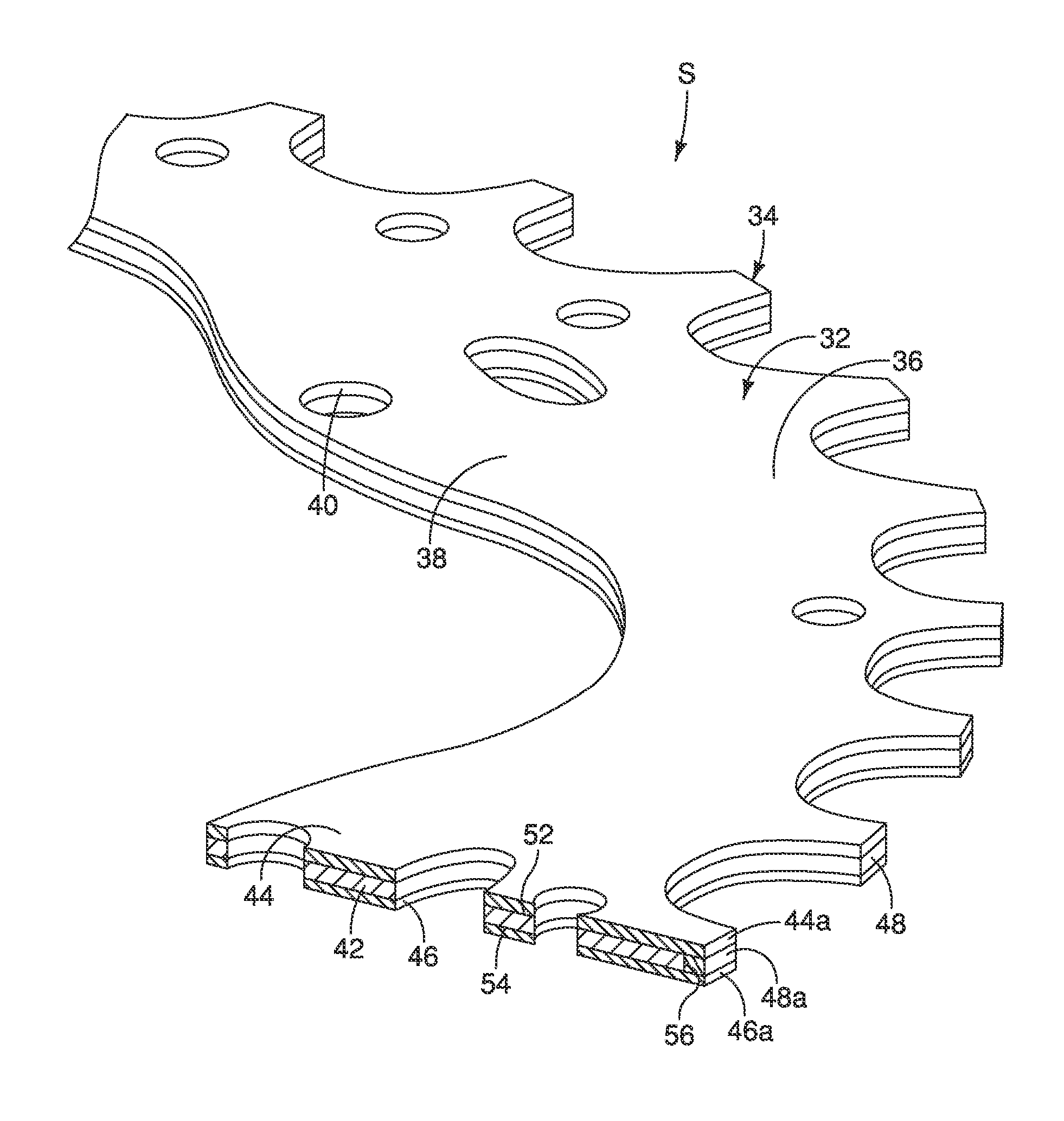
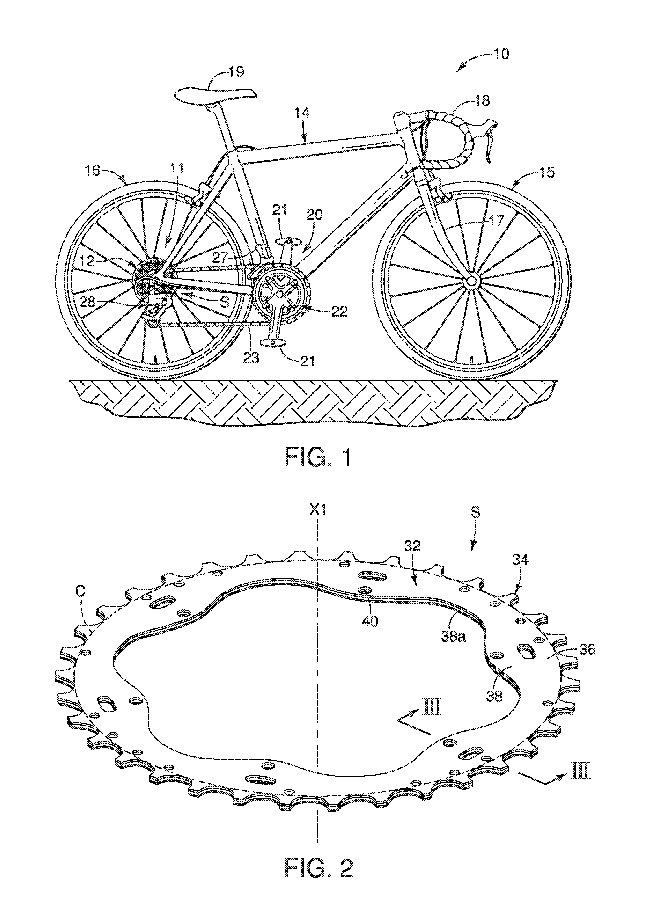
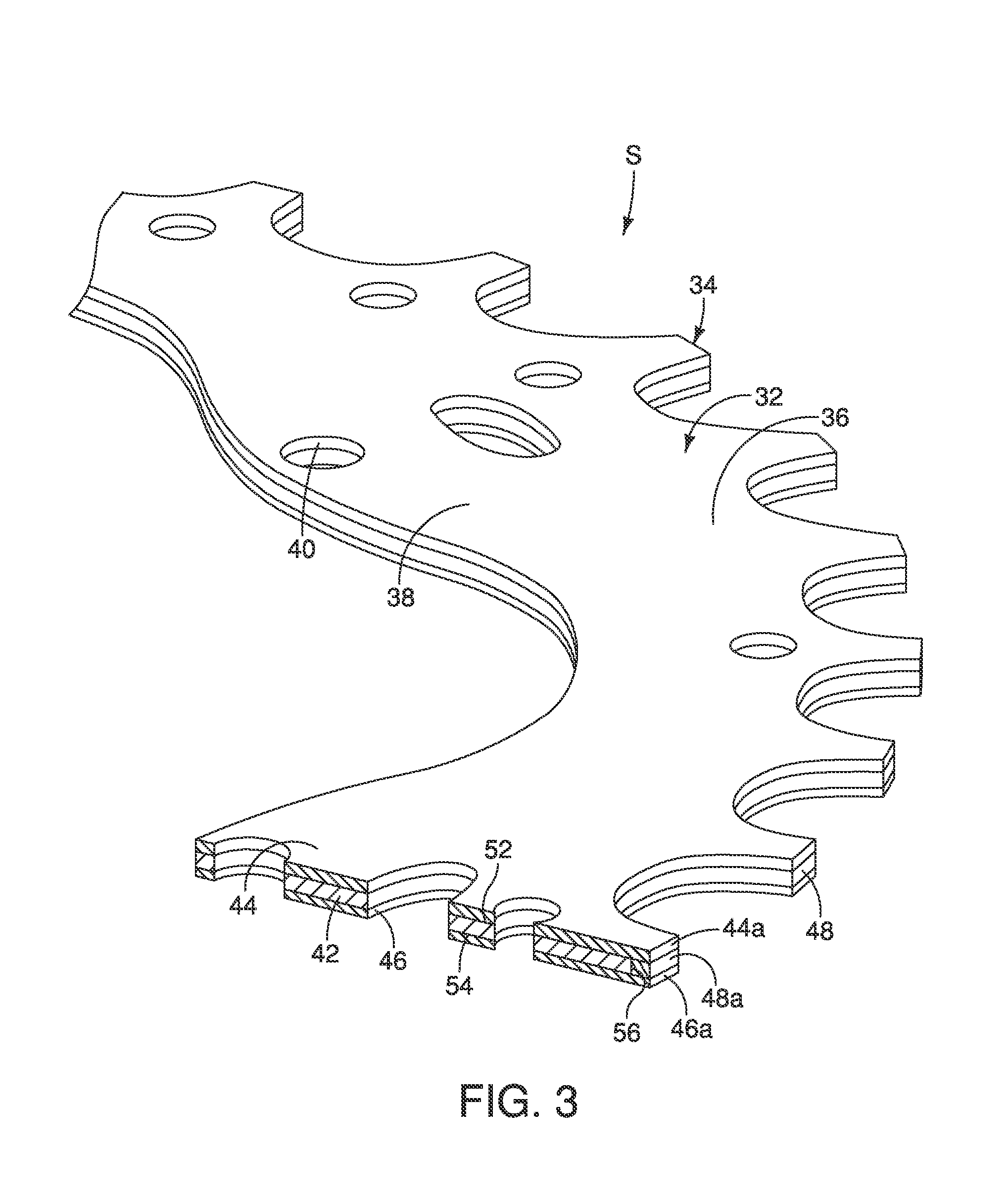
[0171]Referring now to FIGS. 12 to 15, a front sprocket assembly 222 (e.g., a multiple sprocket assembly) in accordance with a third embodiment will now be explained. The front sprocket assembly 222 is basically identical to the front sprocket assembly 22 shown in FIG. 1, except that a sprocket S of the front sprocket assembly 222 includes a multi-layered structure, as explained below.

[0172]In view of the similarity between the first and third embodiments, the parts of the third embodiment that are identical to the parts of the first embodiment will be given the same reference numerals as the parts of the first embodiment. Also, parts of this third embodiment that are functionally identical and / or substantially identical to parts of the first embodiment will be given the same reference numerals but with “200” added thereto. In any event, the descriptions of the parts of the third embodiment that are substantially identical to the parts of the first embodiment may be omitted for the ...

fourth embodiment

[0179]Referring now to FIGS. 16 to 18A, a rear sprocket assembly 312 (e.g., a multiple sprocket assembly) in accordance with a fourth embodiment will now be explained. The rear sprocket assembly 312 is basically identical to the rear sprocket assembly 12 in accordance with the first embodiment, except for a configuration of a sprocket body 332, as explained below.

[0180]In view of the similarity between the first and fourth embodiments, the parts of the fourth embodiment that are identical to the parts of the first embodiment will be given the same reference numerals as the parts of the first embodiment. Also, parts of this fourth embodiment that are functionally identical and / or substantially identical to parts of the first embodiment will be given the same reference numerals but with “300” added thereto. In any event, the descriptions of the parts of the fourth embodiment that are substantially identical to the parts of the first embodiment may be omitted for the sake of brevity. H...


PUM


Abstract

A bicycle sprocket includes a sprocket body, and a plurality of sprocket teeth. At least one of the sprocket teeth includes a first layered member, a second layered member and a third layered member. The first layered member has a first axial surface and a second axial surface. The second layered member is attached to the first axial surface such that the first and second layered members overlap each other in an axial direction as viewed parallel to a rotational axis of the sprocket body. The third layered member is attached to the second axial surface such that the first and third layered members overlap each other in the axial direction as viewed parallel to the rotational axis of the sprocket body. The first layered member has a specific gravity that is less than those of the second layered member and the third layered member.

Description

BACKGROUND[0001]1. Field of the Invention[0002]This invention generally relates to a bicycle sprocket. More specifically, the present invention relates to a bicycle sprocket with a multi-layered structure.[0003]2. Background Information[0004]In recent years, bicycle component manufacturers have been manufacturing bicycle transmissions that have more available speeds to the rider. As the available speeds in the bicycle transmission increases, the number of sprockets installed on the rear wheel also usually increases. While sprockets can be made thinner, a minimum spacing between adjacent sprockets is required to accommodate the chain. Moreover, a rear end of a conventional bicycle frame only has a limited amount of space for mounting the wheel and a rear sprocket assembly. Thus, there is a desire to increase the number gears without changing the dimensions of the conventional bicycle frame. Accordingly, various attempts have been made in order to increase the maximum number of sprock...

Claims


Application Information

Patent Timeline
Patent Type & Authority Patents(United States)
IPC IPC(8): F16H55/30B62M9/10
CPCB62M9/105
Inventor IWAI, TORUSOUWA, MAKOTOYOSHIDA, TOYOSHI
Owner SHIMANO INC
Why Eureka
Try Eureka