Electromechanical assembly for connecting a series of perforating guns for oil and gas wells

a technology of perforating guns and electrical components, applied in the direction of fluid removal, wellbore/well accessories, earthwork drilling and mining, etc., can solve the problems of reducing the quantity of accessories used and the useful life, and achieve the effect of simplifying the connection and assembly of the guns, prolonging the useful life of the connectors, and reducing the quantity of accessories

Active Publication Date: 2016-09-13
TASSAROLI
View PDF3 Cites 29 Cited by
  • Summary
  • Abstract
  • Description
  • Claims
  • Application Information

AI Technical Summary

Benefits of technology

[0010]According to this invention, the mechanical connection between the consecutive guns and between the bottom sub and bottom gun are comprised of tubular adaptors and tubular intermediates, each of which has, respectively, a threaded end joint, and an opposing end joint that employs a bayonet twist lock, formed by a singular reinforced locking bayonet locking tab. This bayonet-locking feature notably extends the useful life of the connectors when compared to the threaded end joints currently used in the industry.
[0011]Also, the design of these connectors reduces the quantity of accessories that are employed, simplifying the connection and assembly of the guns at the well site, creating a more secure system with a longer useful life.
[0012]By having the possibility of assembling a majority of the materials and system in the base, one gains the following advantages:
[0016]Assembly at the base simplifies and decreases the effort by personnel, due to improved climatic, lighting, and logistical conditions than those found in the field.

Problems solved by technology

Also, the design of these connectors reduces the quantity of accessories that are employed, simplifying the connection and assembly of the guns at the well site, creating a more secure system with a longer useful life.

Method used


Image

  • Electromechanical assembly for connecting a series of perforating guns for oil and gas wells
  • Electromechanical assembly for connecting a series of perforating guns for oil and gas wells
  • Electromechanical assembly for connecting a series of perforating guns for oil and gas wells

Examples


Embodiment Construction

[0065]The following is a detailed description of exemplary embodiments to illustrate the principles of the invention. The embodiments are provided to illustrate aspects of the invention, but the invention is not limited to any embodiment. As those skilled in the art will appreciate, the scope of the invention encompasses numerous alternatives, modifications and equivalent; it is limited only by the claims.

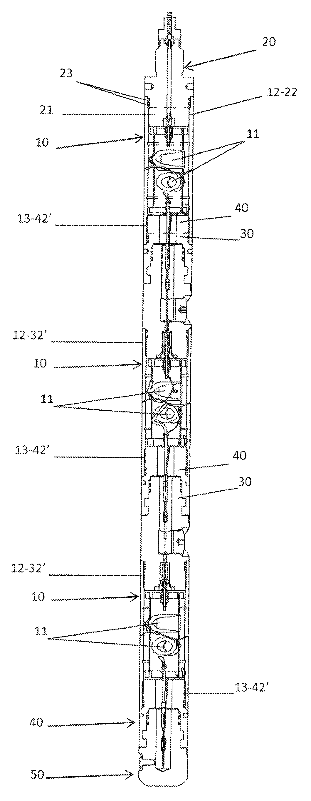
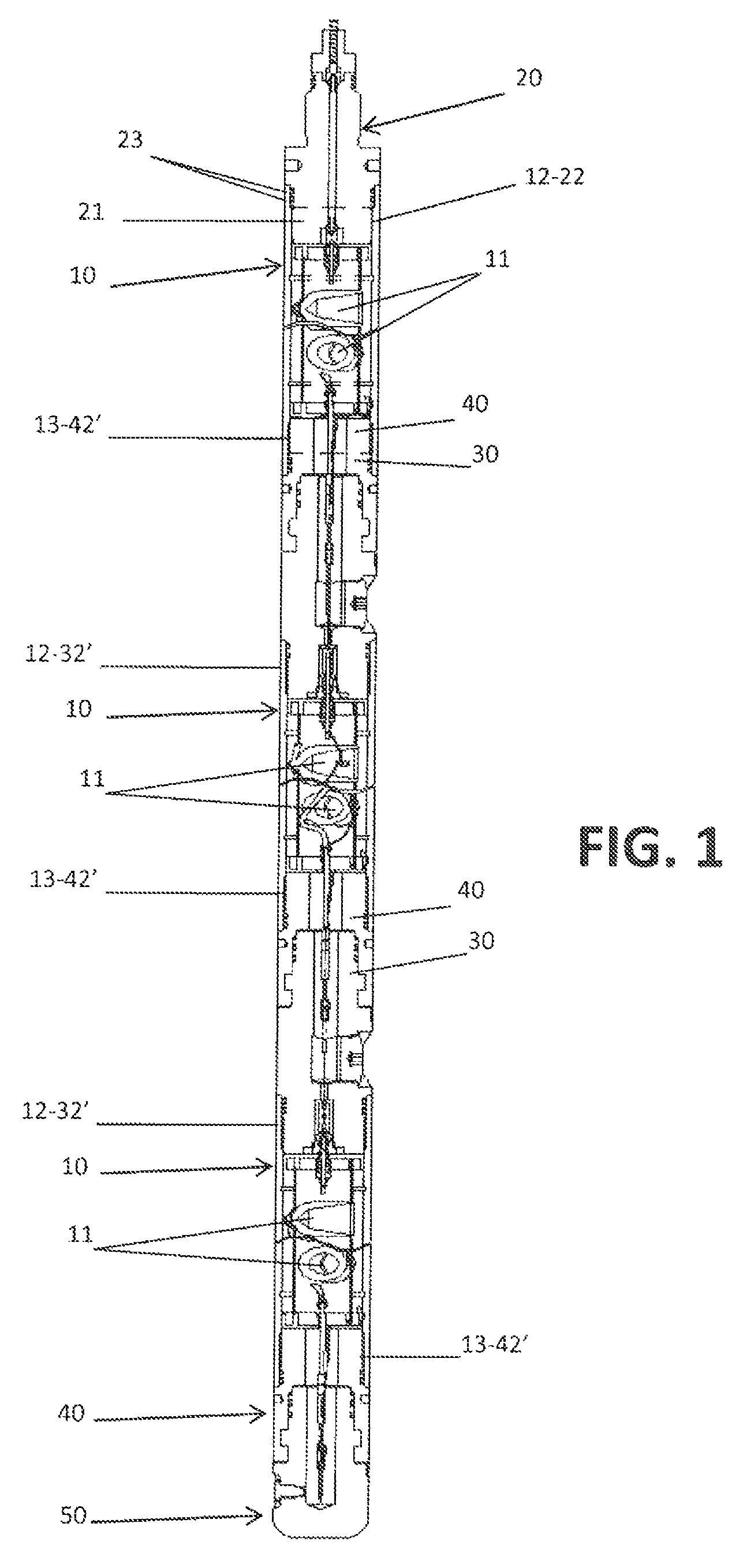
[0066]FIG. 1 illustrates an assembly to be used in the perforation of petroleum producing wells, constituted of three guns (10), a firing head (20), two intermediate pieces (30), three adaptor pieces (40) and a bottom sub (50). The assembly so constituted is the carrier of an electronic circuit for the selective detonation of explosive shaped-charges (11) that are radially positioned in the gun. The constituent elements of said circuit are not described, as they do not form part of the scope of this invention.

[0067]Each gun (10) is a hollow treated steel cylinder whose opposing end...


PUM


Abstract

Mechanical connector for the connection and assembly of guns used in the perforation of petroleum producing wells. Each gun has a hollow cylindrically shaped housing whose ends have threaded joints. Explosive shipped-charges are radially set in respective peripheral slots of the gun. Guns are coaxially joined in vertical position within the casing of the well, forming an assembly that includes the firing head and a bottom sub. The joints between consecutive guns and between the bottom sub and the lowermost gun, include tubular adaptor pieces and intermediaries that have respectively a threaded joint end and an opposing end constituted by a bayonet-type locking joint formed by a single reinforced latching bayonet locking tab.

Description

FIELD OF THE INVENTION[0001]The present invention refers to an electromechanical assembly for connecting a series of guns used in the perforation of petroleum producing wells and more particularly it refers to improvements on the connectors used for assembling the perforating guns.[0002]Perforation of a petroleum producing well consists of the controlled breaking of the metallic casing of the well, the isolating cement surrounding the casing, and the layers of rock in the productive formation by use of explosives housed within perforating-guns; achieving, through bore holes produced by shaped charges, a connection between the depths of the producing zone and the interior of the well.BACKGROUND OF THE INVENTION[0003]The perforation of petroleum producing wells is realized by lowering into the well various metallic perforating-guns of different lengths, whose respective charge carriers are charged with shaped charges, connected by joints and fired in a vertical fashion, one after anot...

Claims


Application Information

Patent Timeline
Patent Type & Authority Patents(United States)
IPC IPC(8): E21B43/116
CPCE21B43/116
Inventor TASSAROLI, CARLOS JOSE
Owner TASSAROLI
Why Eureka
Try Eureka