
Methods and systems for material fixation

a technology of material fixation and system, applied in the field of tendontobone fixation system, can solve the problems of increasing the rate of anterior knee pain, invasive harvesting procedure of btb autograft, and tendons which are torn from their insertion site into bone, etc., and achieves the effect of improving the tendon-bone fixation of hamstring autografts, high fixation of tendon-bone, and convenient us

Active Publication Date: 2016-09-27
CAYENNE MEDICAL INC
View PDF7 Cites 0 Cited by
  • Summary
  • Abstract
  • Description
  • Claims
  • Application Information

AI Technical Summary

Benefits of technology

The invention is a device that improves the fixation of hamstring autografts and other soft tissue ACL reconstruction techniques. It is easy to use, provides high fixation of tendon-bone, and active tendon-bone compression using a single drill hole. The device replicates the native ACL by compressing the tendons against the bone at the aperture of the femoral tunnel, resulting in a shorter graft and increased graft stiffness compared to cortical-only hamstring fixation devices. It also provides strength greater than 1,000 N (Newtons) which is desirable for ACL reconstruction systems. The invention includes a deployment member that advances into the implant and breaks a breakaway tab connecting wing portions together in their undeployed orientation to ensure proper deployment.

Problems solved by technology

In addition, tendons which are torn from their insertion site into bone also frequently require repair.
However, BTB reconstructions result in an increased rate of anterior knee pain post-surgically for periods of up to three years after reconstruction.
Additionally, the harvest procedure for the BTB autograft is invasive, and can be difficult to perform.
Many systems have addressed some of the problems associated with ACL reconstruction using hamstring tendons, but there is not one system that addresses them all.
However, it does require additional accessories and additional people to perform the procedure, and does not replicate the native ACL due to a lack of tendon-to-bone compression at the aperture as well as additional length of tendon between fixation points.
This does create more intimate contact between the tendon and bone, but does not offer real compression at the aperture.
However, the pull-out strength and stiffness of the repair are significantly lower than in the preceding systems.

Method used


Image

  • Methods and systems for material fixation
  • Methods and systems for material fixation
  • Methods and systems for material fixation

Examples


Embodiment Construction

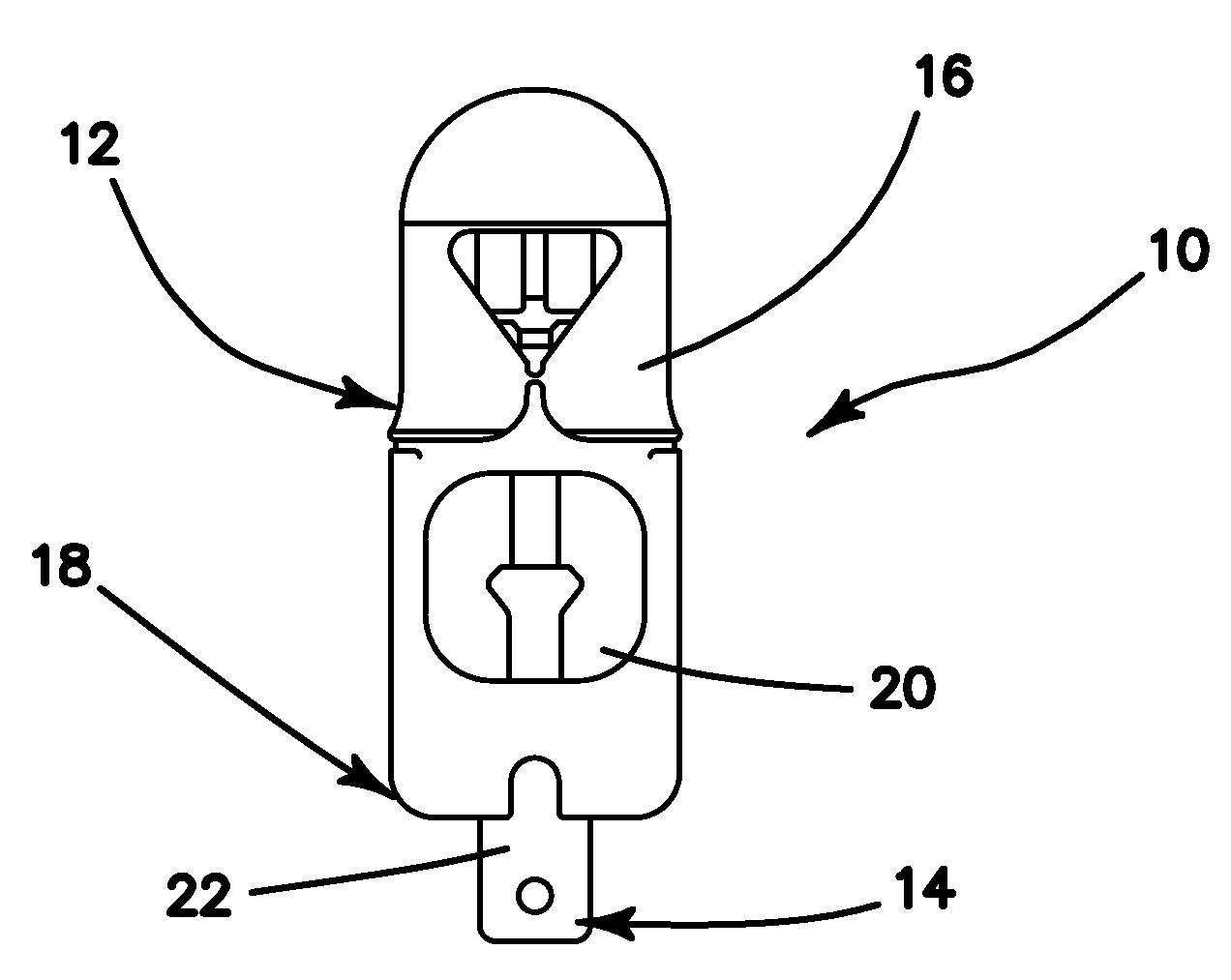
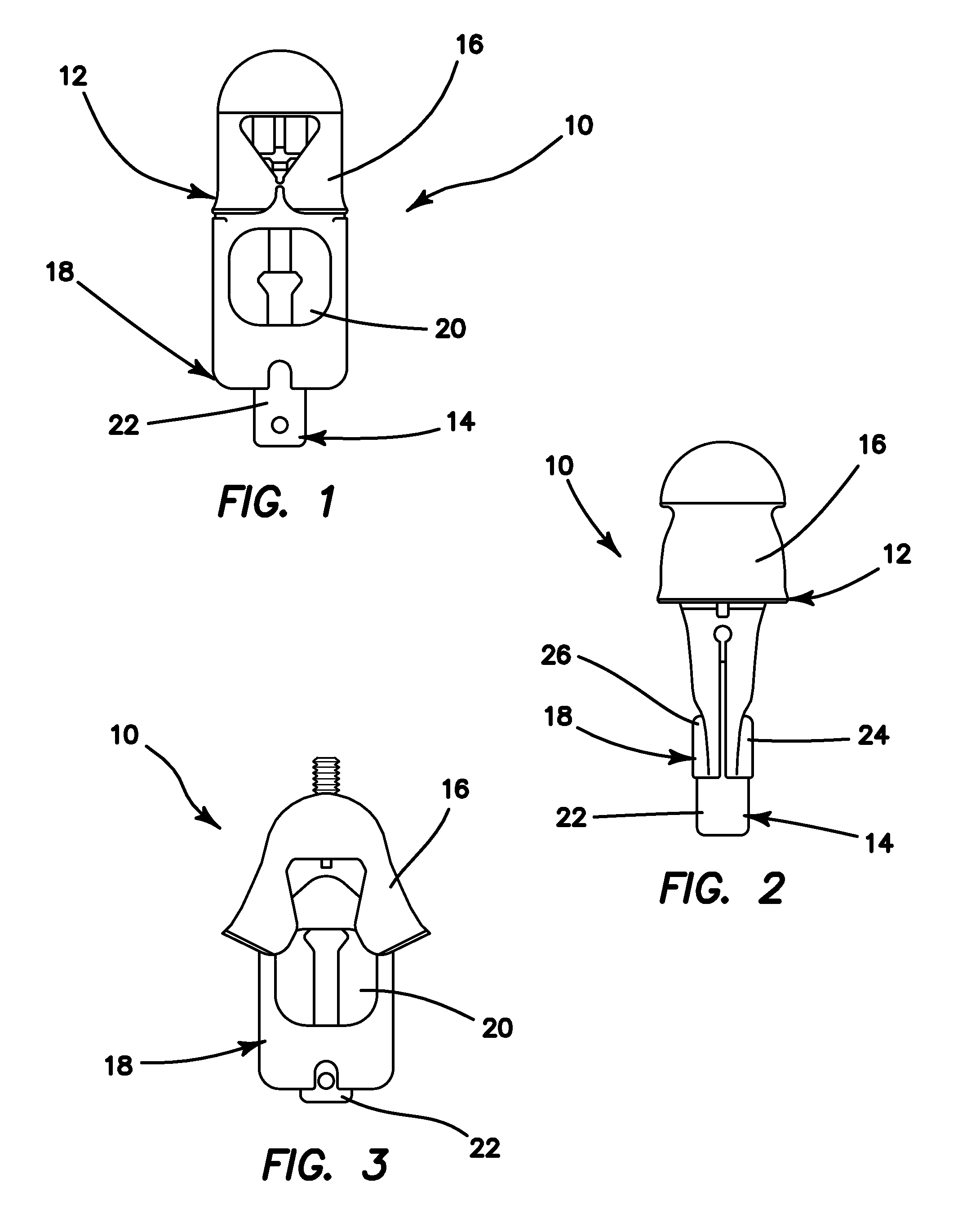
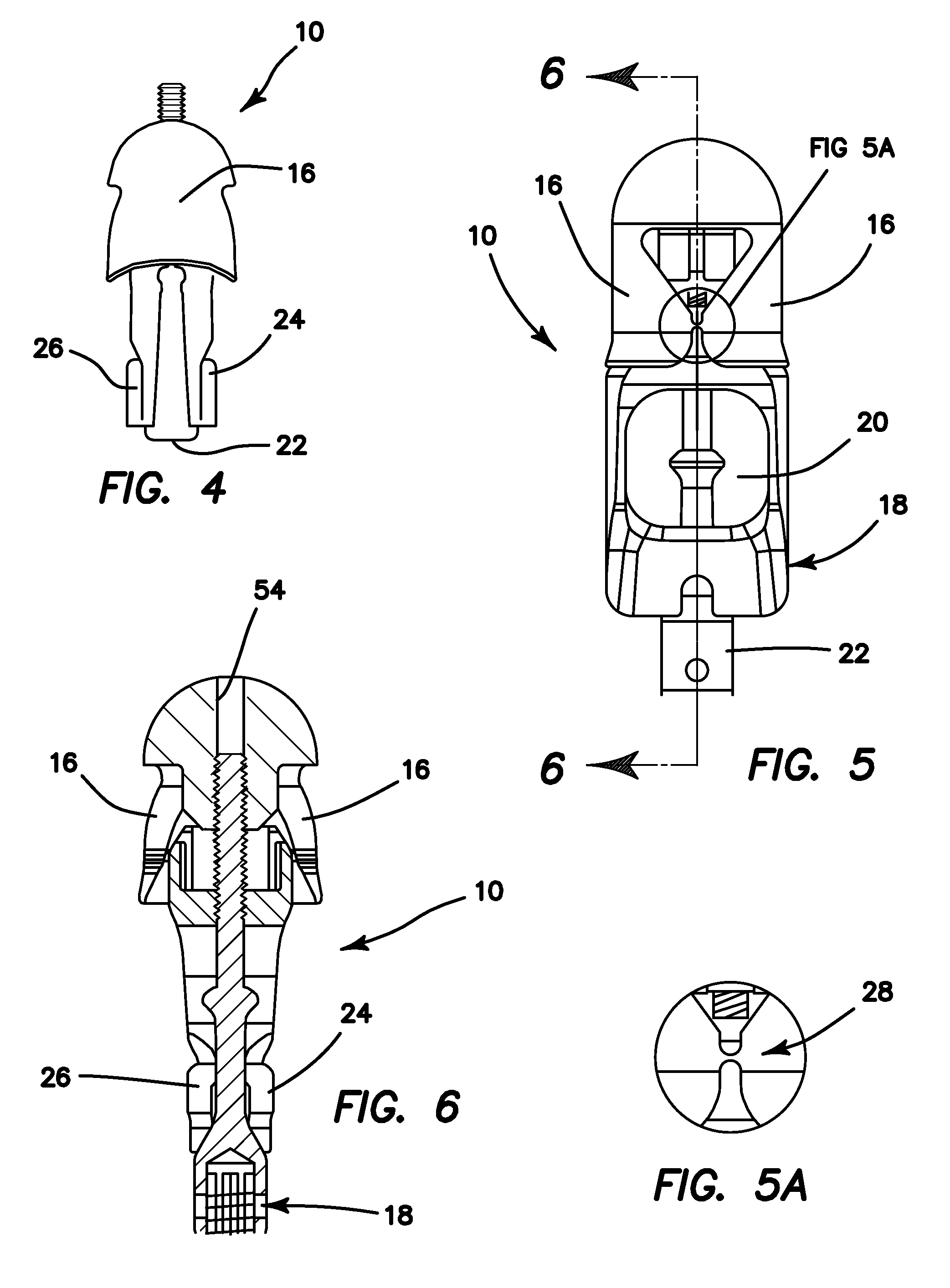
[0051]Referring now more particularly to the drawings, an implant 10 constructed in accordance with the principles of the present invention, having a body 12 comprising three separate major components. These components comprise a quad lead screw 14, wings 16, and a body wedge 18. Tendon eyelets 20 are provided for the loading of tendons thereinto prior to insertion of the implant 10 into a bone tunnel. When the implant 10 is placed into a bone tunnel, the screw 14 is rotated clockwise until a head 22 of the screw 14 slides between portions 24, 26 of the body wedge 18. This expands the base of the implant by forcing the wedge portions 24, 26 outwardly, thereby acting to compress the tendon against the bone tunnel walls. As the screw 14 continues to rotate, the wings 16 slide apart over the body wedge 18 and engage with the walls of the bone tunnel to anchor the implant 10 in place within the tunnel. The engagement of the wings 16 into the bone is what gives the implant the majority o...


PUM


Abstract

A system and method for making an orthopedic repair by fixing a soft tissue graft to bone, utilizes an implant including a body wedge having first and second outwardly expandable wedge portions, a wing portion having outwardly expandable wings, and a deployment member which is movable distally into the implant to deploy the wedge portions and the wings into an expanded deployed orientation.

Description

[0001]This application claims the benefit under 35 U.S.C. 119(e) of the filing date of Provisional U.S. application Ser. No. 61 / 717,569, entitled Methods and Systems for Material Fixation, filed on Oct. 23, 2012, which application is herein expressly incorporated herein by reference, in its entirety.[0002]This application is also related to commonly assigned U.S. Pat. Nos. 7,879,094 and 8,206,446, both herein expressly incorporated by reference in their entirety.BACKGROUND OF THE INVENTION[0003]The present invention relates generally to devices, systems and methods for material fixation. More particularly, the invention relates to a new and novel tendon-to-bone fixation system.[0004]One of the most common needs in orthopedic surgery is the fixation of tendon to bone. The fixation of diseased tendons into a modified position is called tenodesis and is commonly required in patients with injury to the long head of the biceps tendon in the shoulder. In addition, tendons which are torn f...

Claims


Application Information

Patent Timeline
Patent Type & Authority Patents(United States)
IPC IPC(8): A61F2/08
CPCA61F2/0811A61F2002/0835A61F2002/0852A61F2002/0882A61F2250/0071A61F2002/0888
Inventor BAIRD, KEVIN N.HARPER, DEREK J.
Owner CAYENNE MEDICAL INC
Learn More