Self-leveling utility platform

a utility platform and self-leveling technology, applied in the field of self-leveling utility platforms, can solve the problems of affecting the dining experience, threw the support surface off the ground, unsafe conditions for users and work products, etc., and achieves the effect of convenient storage and transportation, secure and stable fixation of the position of each leg, and easy actuation

Active Publication Date: 2016-09-27
G C HOYLE CO LLC
View PDF31 Cites 11 Cited by
  • Summary
  • Abstract
  • Description
  • Claims
  • Application Information

AI Technical Summary

Benefits of technology

[0008]Exemplary embodiments of adjustable support assemblies include a support element, two or more legs, and corresponding leg exchange brackets, each adapted for attachment to a support element and a leg. In an exemplary embodiment, a leg includes a stem that is attached by insertion into a receiving portion of a leg exchange bracket, enabling the leg to rotate within the leg exchange bracket around an insertion axis. By differential rotation of each of the two or more legs within its corresponding leg exchange bracket, the user of the support assembly can adjust the elevation of ground contact points on the legs so as to accommodate varying terrain and uneven ground conditions. Rotation of the legs also permits the support assembly to be adapted to lie flat relative to the support element so that the entire assembly may be stored and transported more easily than in its erected state. Adjustment is achieved by actuation of a simple bolt, toggle or nut that is easily actuated without a tool and then lockable to ensure secure and stable fixation of the position of each leg.

Problems solved by technology

Achieving a steady and level support surface has long been a challenge.
If one or more of the legs of a support structure is not firmly contacting the underlying terrain, the support structure will be disposed to wobble, tilt or sway, thereby destabilizing the structure and throwing the support surface off level.
Most people have experienced this problem with a wobbly cafe or picnic table that adversely affects the dining experience.
Additionally, if the support structure is used for work that involves sawing or other reciprocating motions, the instability caused by uneven terrain combined with the vibrational motion can cause the support structure to migrate on the terrain and possibly overturn, causing unsafe conditions for the user and the work product.
Finally, if one or more of the legs of a support structure is not firmly contacting the underlying terrain, then independent of the use of the support surface, the structural integrity of the support structure can be compromised, leading to structural damage and potential collapse.
A conventional sawhorse is one example of a work surface that can present danger to a user if it is not stable.
But because a typical sawhorse assembly cannot be readily adjusted for adaptation to variable terrain, it may present a work surface that is ultimately unsteady and prone to tipping.
Such instability presents hazards to both the user and the job-site work product, particularly when sharp and powered tools are being used.
The static design of the sawhorse is also inefficient and cumbersome for purposes of portability and storage due to its overall shape.
Indeed, because of its awkward shape and the attendant difficulty with storage and transportation, the sawhorse is often constructed and deconstructed on the job site.
In one specific example, outdoorsman encounter widely variable terrain that that can make it difficult to achieve a safe and stable tabletop or other surface suitable for cooking, eating, cleaning fish, dressing game, gear maintenance and storage, and the like.
While these designs can provide enhanced portability and storage, and enable achieving an improved level surface, such designs can suffer from compromised stability, lack of ease of use, and increased cost and complication in their manufacture.

Method used


Image

  • Self-leveling utility platform
  • Self-leveling utility platform
  • Self-leveling utility platform

Examples


Embodiment Construction

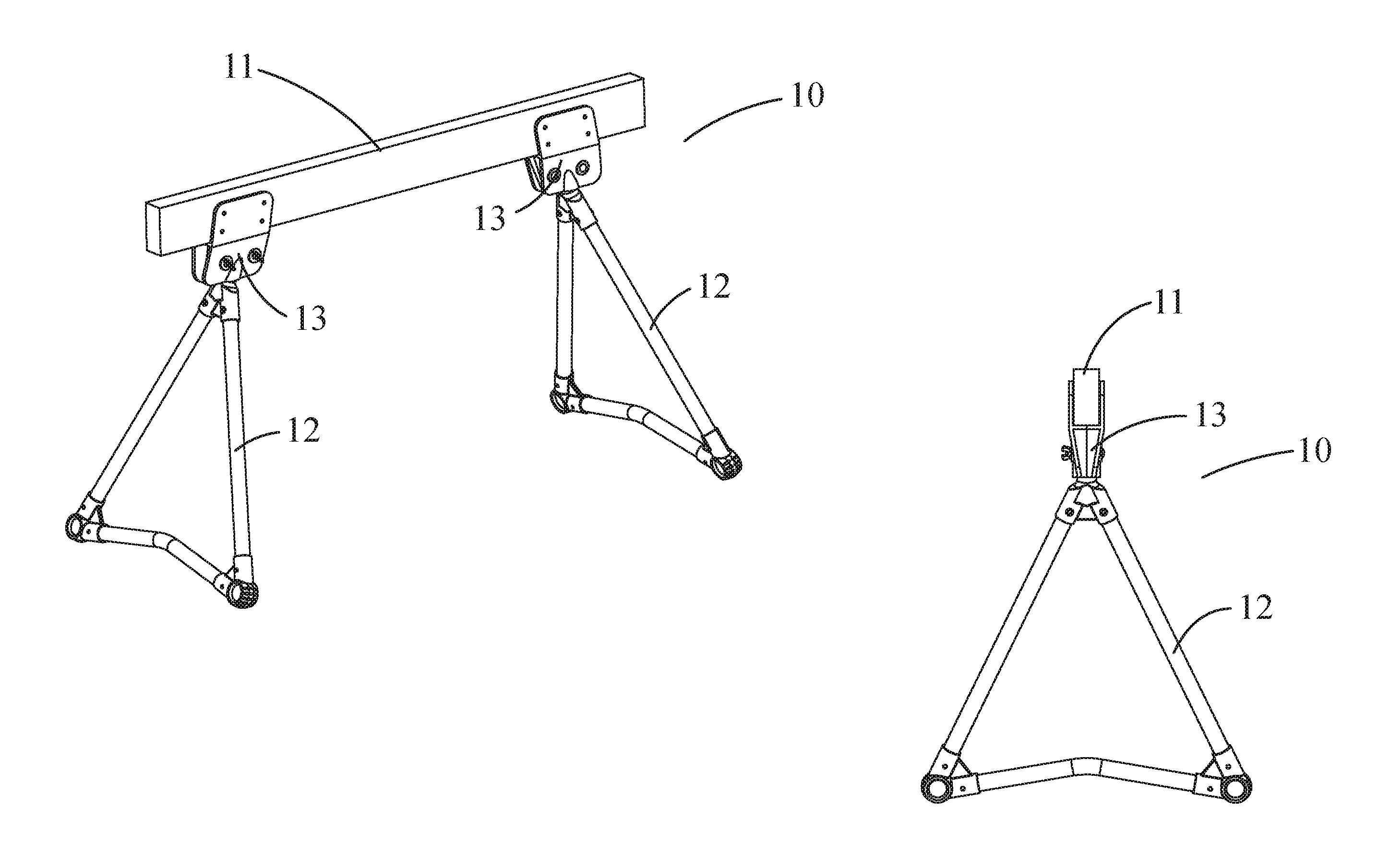
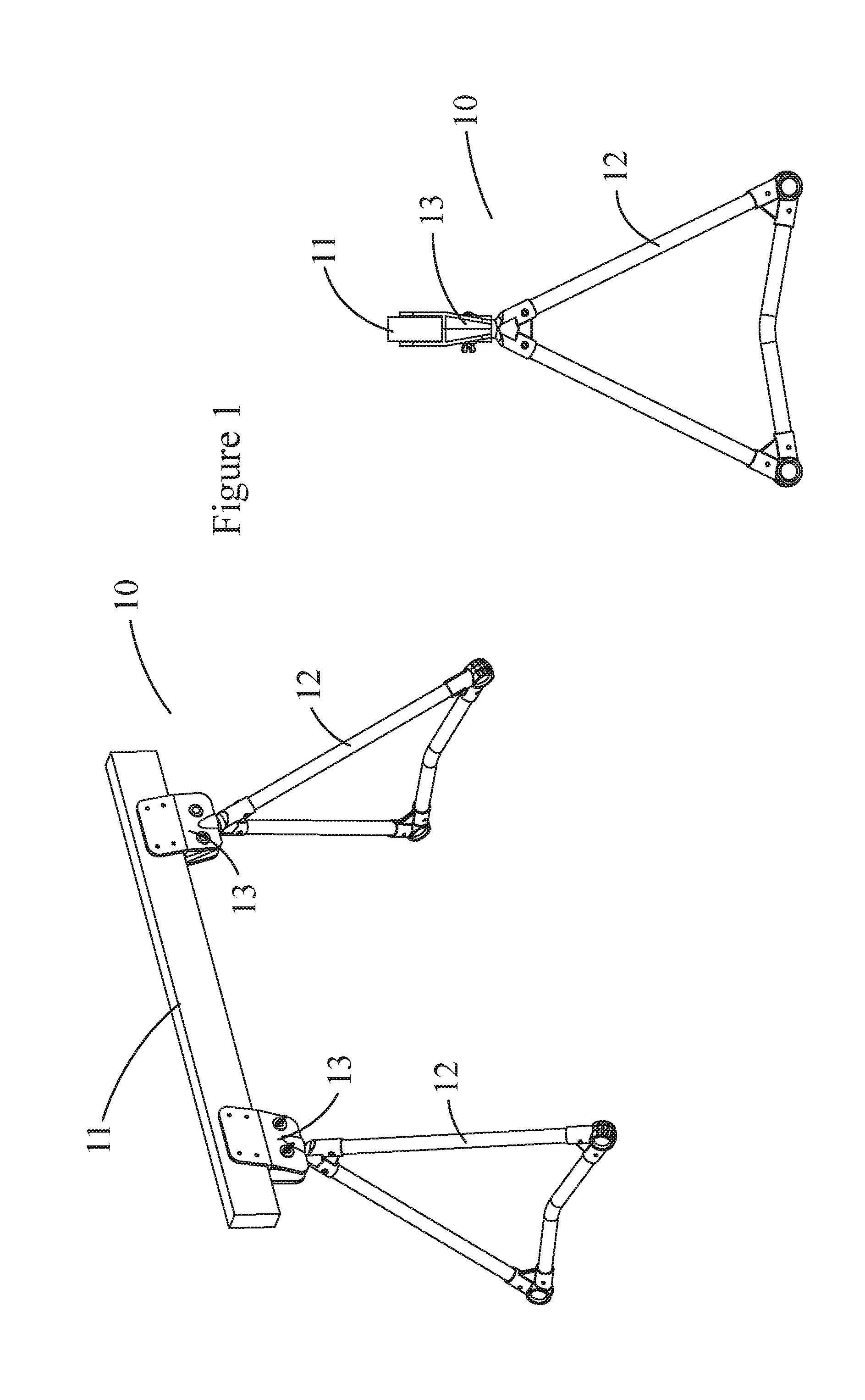
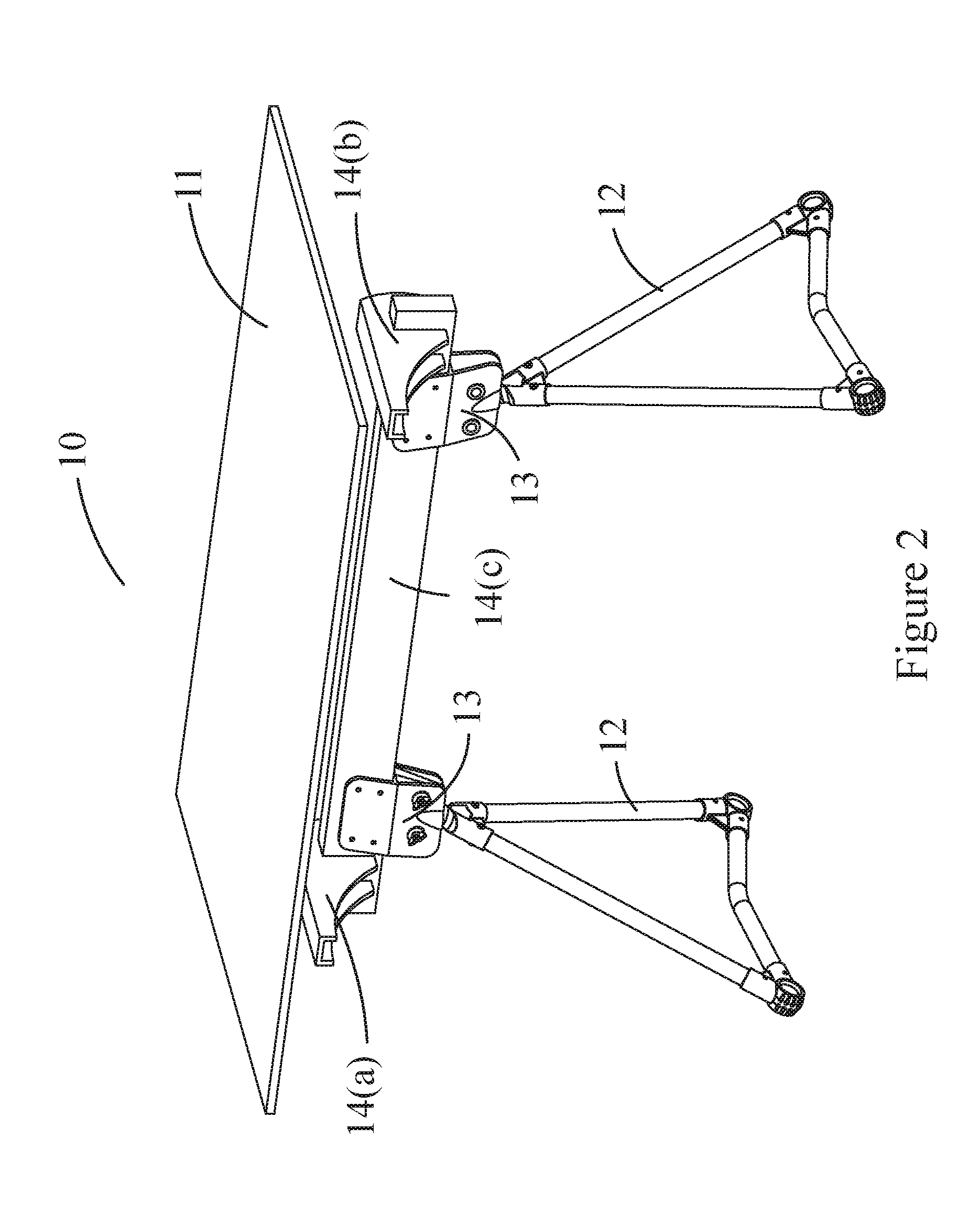
[0033]Exemplary embodiments of the present invention are now described with reference to the Figures. Reference numerals are used throughout the detailed description to refer to the various elements and structures. Although the following detailed description contains many specifics for the purposes of illustration, a person of ordinary skill in the art will appreciate that many variations and alterations to the following details are within the scope of the invention. Accordingly, the following embodiments of the invention are set forth without any loss of generality to, and without imposing limitations upon, the claimed invention.

[0034]The general inventive concepts will now be described with occasional reference to the exemplary embodiments of the invention. This general inventive concept may, however, be embodied in different forms and should not be construed as limited to the embodiments set forth herein. Rather, these embodiments are provided so that this disclosure will be thor...


PUM


Abstract

A self-adjusting support assembly for use on uneven surfaces that includes a support element; at least one pivoting leg assembly positioned beneath the support element; and at least one self-adjusting attachment assembly that connects the support element to the at least one pivoting leg assembly, and wherein the at least one self-adjusting attachment assembly further includes: at least one bracket that is adapted to attach to the support element, and wherein the at least one bracket further includes: a receiving channel formed therein that is positioned along an angled axis of insertion, and a locking ridge positioned in the receiving channel; and a proximal head portion that is adapted to rotationally cooperate with at least one bracket and to receive the at least one pivoting leg assembly, and wherein the proximal head portion further includes: a flange formed at one end thereof that rotationally engages the locking ridge; a stem positioned beneath the flange, wherein the stem rotationally engages the receiving channel; and a receiving portion positioned beneath the stem that is adapted to receive the at least one leg assembly.

Description

CROSS-REFERENCE TO RELATED APPLICATIONS[0001]This patent application is a continuation-in-part of U.S. patent application Ser. No. 13 / 889,093 filed on May 7, 2013 and entitled “Adjustable Assembly for Providing All-Terrain Support to Tables and Other Structures”, the disclosure of which is hereby incorporated by reference herein in its entirety and made part of the present U.S. utility patent application for all purposes.BACKGROUND OF THE INVENTION[0002]Achieving a steady and level support surface has long been a challenge. Conventional support legs are static—they are not designed to be adjusted which means that the stability of the table or other rest or work surface relies on the contact points of the legs all resting on a single plane. If one or more of the legs of a support structure is not firmly contacting the underlying terrain, the support structure will be disposed to wobble, tilt or sway, thereby destabilizing the structure and throwing the support surface off level. Most...

Claims


Application Information

Patent Timeline
Patent Type & Authority Patents(United States)
IPC IPC(8): F16L3/00F16M11/38A47B13/02B25H1/02
CPCF16M11/38A47B13/02B25H1/02A47B9/16B25H1/04B25H1/06
Inventor HOYLE, GARY
Owner G C HOYLE CO LLC
Why Eureka
Try Eureka