
Seat assembly having heating element providing electrical heating of variable temperature along a predetermined path to a zone

a technology of variable temperature and heating element, which is applied in the direction of seat heating/ventilation device, ohmic resistance heating, vehicle arrangement, etc., can solve the problems of large power consumption of conventional heating element, and consistent amount of power per unit length, so as to achieve a less power consumption, minimize power consumption, and maximize power consumption

Active Publication Date: 2016-10-04
LEAR CORP
View PDF21 Cites 2 Cited by
  • Summary
  • Abstract
  • Description
  • Claims
  • Application Information

AI Technical Summary

Benefits of technology

The seat assembly has a heating element that provides comfortable heating along the surface of the seat. The heating element consumes less power than traditional heating elements, resulting in minimized power consumption. The heating element maximizes comfort for the occupant and minimizes discomfort. It achieves this by focusing the heating to areas of the seat that are less exposed to electrical heating, such as between winding portions of the heating element. This reduces temperature gaps on the seat surface, resulting in increased comfort for the occupant.

Problems solved by technology

In effect, conventional heating elements consume a consistent amount of power per unit length, i.e., per meter.
However, conventional heating elements have a variety of disadvantages.
First, conventional heating elements consume a large amount of power.
Second, conventional heating elements can frequently provide discomfort to an occupant of the seat assembly.
Therefore, those regions of the seating surface which are less exposed to electrical heating are often cooler than surrounding areas thereby causing a temperature differential, or temperature gap in the region.
The occupant senses the temperature gap on the seating surface which, in effect, causes discomfort to the occupant.

Method used


Image

  • Seat assembly having heating element providing electrical heating of variable temperature along a predetermined path to a zone
  • Seat assembly having heating element providing electrical heating of variable temperature along a predetermined path to a zone
  • Seat assembly having heating element providing electrical heating of variable temperature along a predetermined path to a zone

Examples


Embodiment Construction

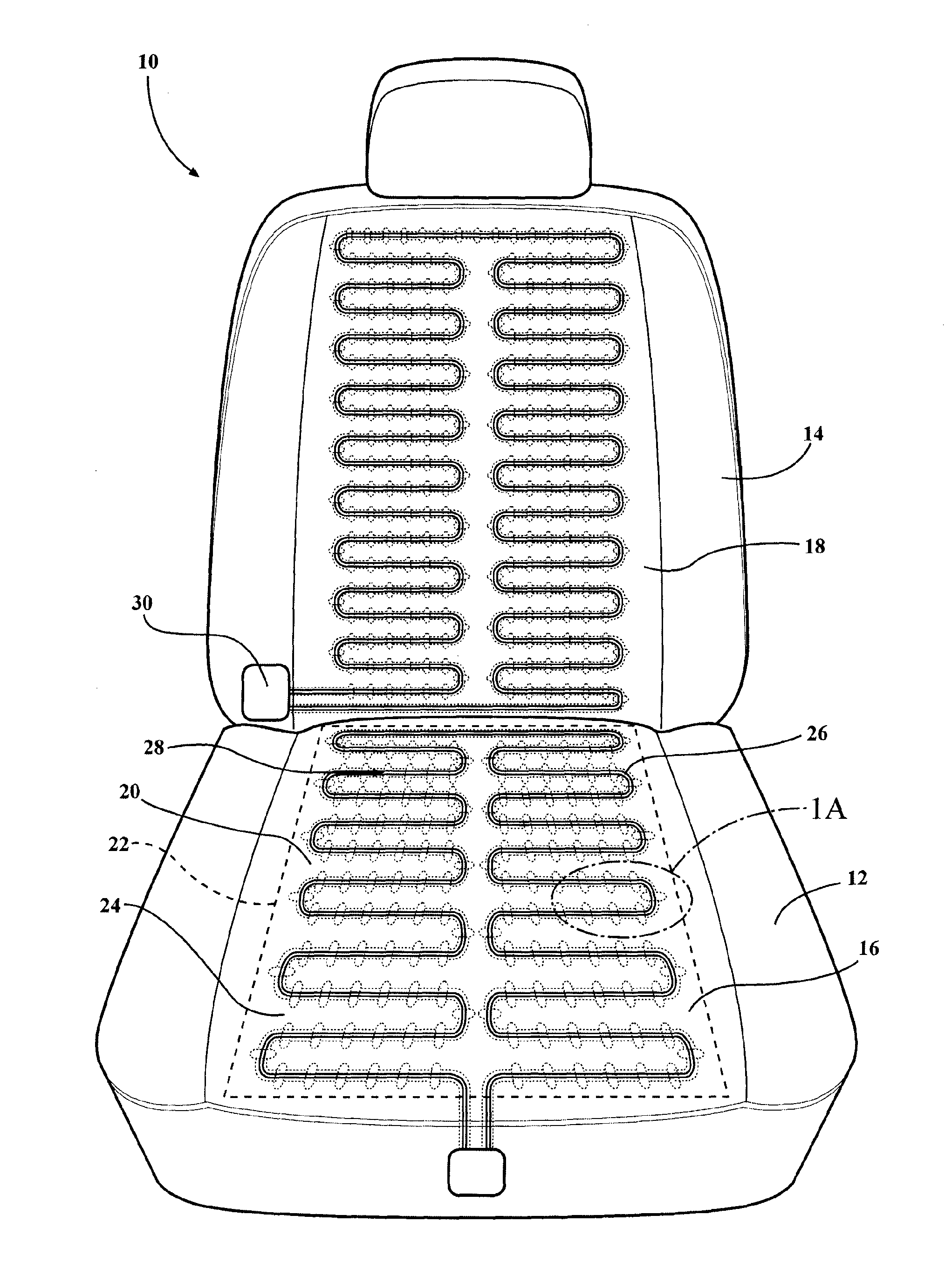
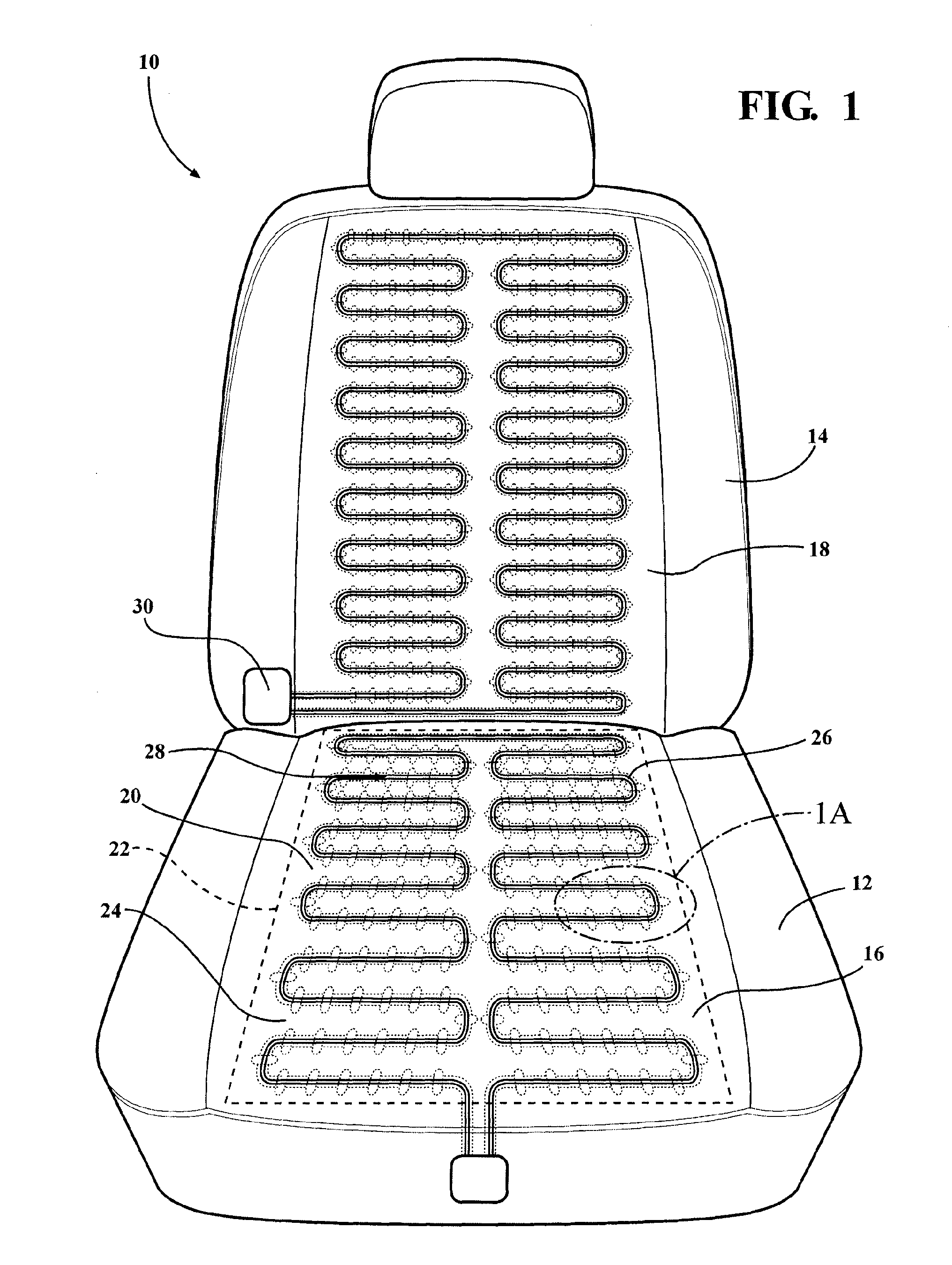
[0024]Referring to the Figures, wherein like numerals indicate like or corresponding parts throughout the several views, a vehicular component is generally shown at 10 in FIG. 1. In the embodiment as shown in FIG. 1, the vehicular component is further defined as seat assembly. For simplicity, the vehicular component hereinafter will be described and numbered according to the seat assembly embodiment, as shown in FIG. 1. However, the vehicular component may include any other suitable device in a vehicle which is heated, such as a steering wheel, and the like.

[0025]The seat assembly 10 is utilized in a vehicle, such as an automobile. The seat assembly 10 includes a seat bottom 12 and a seat back 14 which is coupled to the seat bottom 12. The seat bottom 12 has a bottom seating surface 16 and the seat back 14 has a back seating surface 18.

[0026]The vehicular component has at least one zone 20 which is temperature controlled. In instances where the vehicular component is the seat assemb...


PUM


Abstract

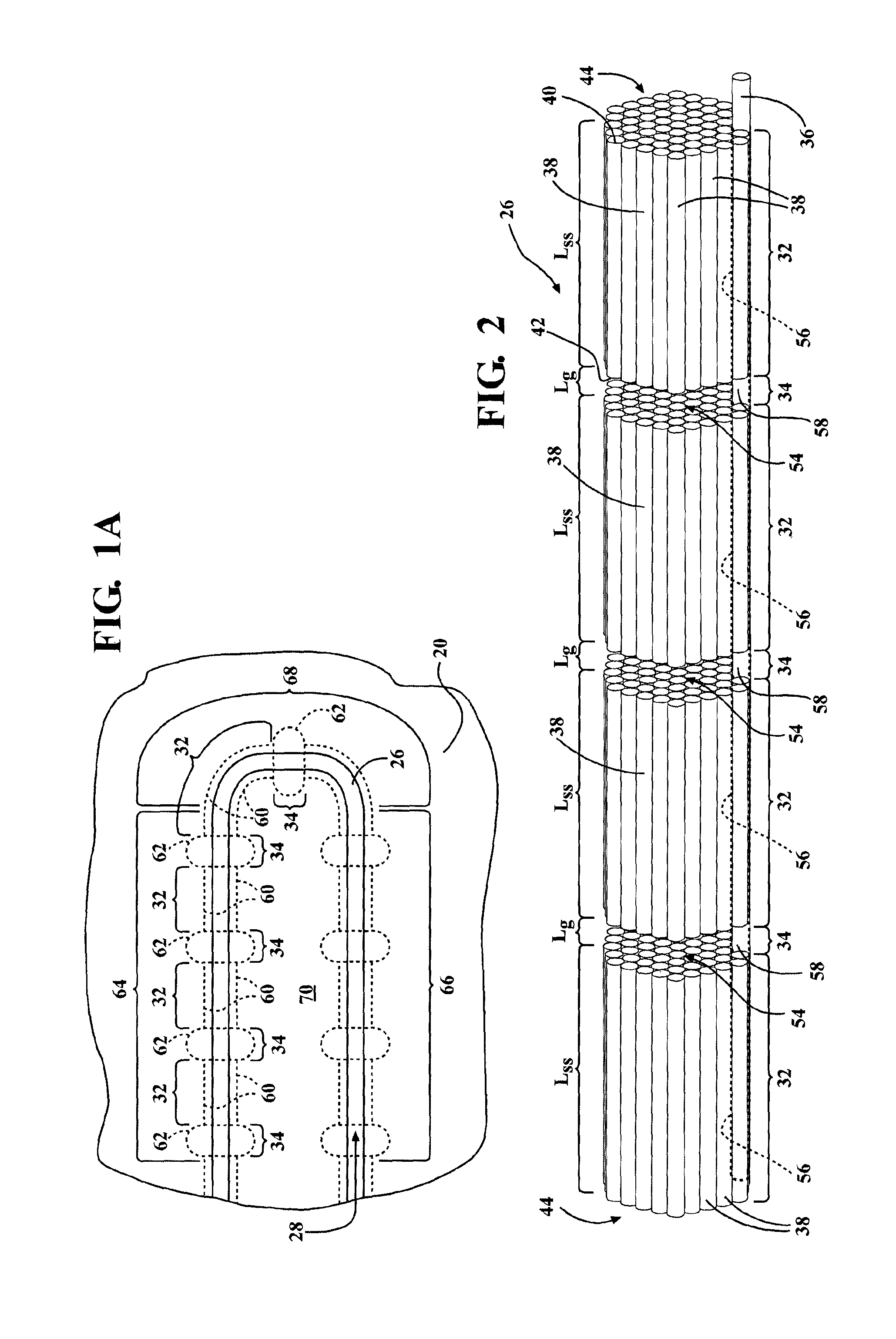
A seat assembly is disclosed which has a heating element disposed along a predetermined path in a zone of a bottom seating surface or back seating surface. The heating element provides electrical heating of variable temperature along the predetermined path to the zone. The heating element includes first and second sections continuously alternating along the predetermined path. Each of the first sections provides electrical heating to the zone at a first temperature and each of the second sections provides electrical heating to the zone at a second temperature which is greater than the first temperature.

Description

CROSS REFERENCE TO RELATED APPLICATIONS[0001]This application is the U.S. National Stage of International Patent Application No. PCT / IB2013 / 000052, filed on Jan. 15, 2013, the disclosure of which is hereby incorporated by reference.BACKGROUND OF THE INVENTION[0002]1. Field of the Invention[0003]The subject invention generally relates to seat assembly having a seating surface with a zone which is temperature controlled, and more specifically, with the heating element disposed in the zone along a predetermined path for providing electrical heating of variable temperature along the predetermined path to the zone.[0004]2. Description of Related Art[0005]Nearly every vehicle today has a seat assembly with a seating surface having a seat back and a seat bottom. Often, the seat back and seat bottom each have a zone which is temperature controlled. A heating element conventionally is disposed along a winding path within the zone for providing electrical heating to the zone. The heating elem...

Claims


Application Information

Patent Timeline
Patent Type & Authority Patents(United States)
IPC IPC(8): B60N2/56H05B3/34H05B3/56
CPCB60N2/5685H05B3/34H05B3/56H05B2203/029H05B2203/037
Inventor TUSKES, MILAN
Owner LEAR CORP
Learn More