
Vehicle collision determination apparatus

a technology of collision determination and vehicle, which is applied in the direction of vehicular safety arrangments, pedestrian/occupant safety arrangements, vehicle components, etc., can solve the problems of unsatisfactory, disclosed determination apparatus, etc., and achieve the effect of improving accuracy, reducing collision energy, and easy to determine collision severity

Active Publication Date: 2016-10-04
HONDA MOTOR CO LTD
View PDF11 Cites 6 Cited by
  • Summary
  • Abstract
  • Description
  • Claims
  • Application Information

AI Technical Summary

Benefits of technology

The invention is a vehicle collision determination apparatus that uses sensors in the vehicle to determine the severity of a frontal collision. The apparatus can accurately determine the severity of a high-speed ODB frontal collision (which occurs at a speed of 150-200 km / h) as being "low" by analyzing the difference between the output of two sensors. The apparatus can use this information to control the operation of airbags and seatbelt pre-tensioners to protect occupants of the vehicle during a collision. By providing the sensors on the same structural member of the vehicle body skeleton, the apparatus can reduce the amount of noise in the sensor output. Additionally, the apparatus may include first and second band-pass filters to enhance the difference between the sensor outputs.

Problems solved by technology

The collision determination apparatus disclosed in JP 2006-044432 is, however, not fully satisfactory in that the airbag deployment determination means cannot discriminate a high-speed ODB (offset deformable barrier) frontal collision where the vehicle is made to collide head-on on the driver's side with an aluminum honeycomb structure at 64 km / h and a slant head-on collision where the vehicle is made to collide head-on on the driver's side with a slanting concrete barrier at 48 km / h.

Method used


Image

  • Vehicle collision determination apparatus
  • Vehicle collision determination apparatus
  • Vehicle collision determination apparatus

Examples


Embodiment Construction

[0038]Certain preferred structural embodiments of the present invention will be described in detail below, by way of example only, with reference to the accompanying sheets of drawings.

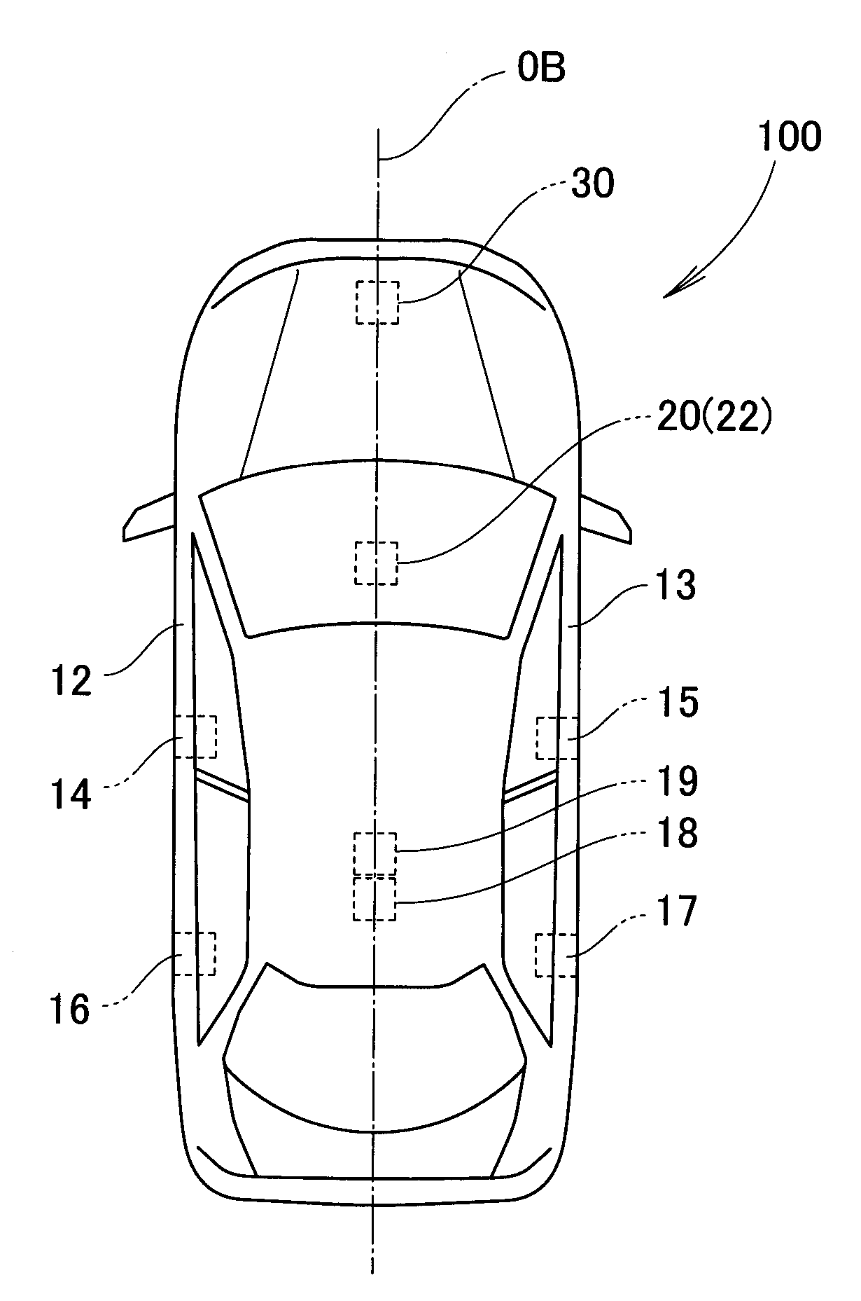
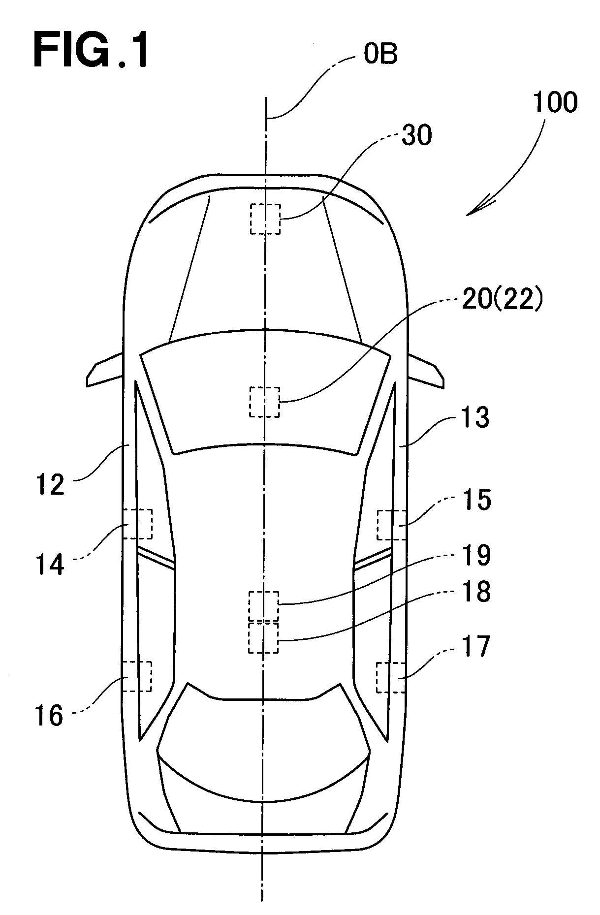
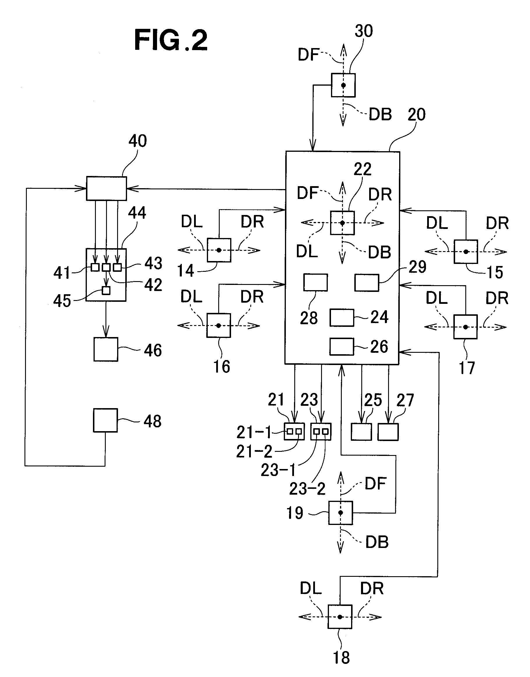
[0039]FIG. 1 shows in plan view an arrangement of a plurality of sensors provided on a vehicle. The vehicle 100 shown in FIG. 1 is equipped with a vehicle collision determination unit 20 which is configured to determine a collision of the vehicle. The vehicle collision determination unit 20 is disposed on a central portion of the vehicle 100. The vehicle collision determination unit 20 may be provided on a floor of a cabin of the vehicle 100 and may incorporate a first floor sensor 22 shown in FIG. 2. As shown in FIG. 1, a front sensor 30 is provided on a front part of the vehicle 100. The vehicle collision determination unit 20 shown in FIG. 1 may determine as to whether or not a frontal collision of the vehicle occurs based on only an output of the first floor sensor 22 or an output of the front sen...


PUM


Abstract

A vehicle collision determination apparatus includes a first sensor and a second sensor provided in a cabin of a vehicle, and a determining portion that determines severity of a frontal collision of the vehicle based on the difference between an output from the first sensor and an output from the second sensor. The output from the first sensor includes a first acceleration in a backward direction of the vehicle, and the output from the second sensor includes a second acceleration in the backward direction of the vehicle. The first sensor and the second sensor are arranged along the backward direction.

Description

FIELD OF THE INVENTION[0001]The present invention relates to a vehicle collision determination apparatus configured to determine a collision of a vehicle using two floor sensors provided in a cabin of the vehicle. Especially, the term “collision” used herein shall be interpreted as including a frontal collision where a front end (e.g. bumper face) of the vehicle is made to collide with a barrier (e.g. vehicle, wall, etc.), and the term “determination” used herein shall be interpreted as including determination of collision severity at the event of a frontal collision.BACKGROUND OF THE INVENTION[0002]Vehicle collision determination apparatuses are known as disclosed, for example, in Japanese Patent Application Laid-open Publication (JP-A) No. 2006-044432. The vehicle collision determination apparatus disclosed in JP 2006-044432 takes the form of a vehicle occupant protection apparatus equipped with a front G sensor, a floor G sensor, and an airbag deployment determination means. The ...

Claims


Application Information

Patent Timeline
Patent Type & Authority Patents(United States)
IPC IPC(8): B60R21/0132
CPCB60R21/0132
Inventor OKAMURA, KENYU
Owner HONDA MOTOR CO LTD
Learn More