
Rim replacing device in tire balance measuring device

a technology of tire balance measurement and rim replacement, which is applied in vehicle tyre testing, vehicle wheel testing, instruments, etc., can solve the problems of time-consuming and inconvenient exchange, troublesome correction task, and unbalance state of rotation part of tire balance measurement apparatus itself, so as to achieve convenient and prompt exchange

Active Publication Date: 2016-10-11
YAMATO SCALE CO LTD
View PDF16 Cites 1 Cited by
  • Summary
  • Abstract
  • Description
  • Claims
  • Application Information

AI Technical Summary

Benefits of technology

[0005]In such a way, in the conventional rim exchange, there is a need for a centering task of the lower rim and a re-correction task. Thus, the rim exchange is time-consuming and inconvenient, and working efficiency of the measurement apparatus and a measurement line is lowered.
[0015]In such a way, according to the present invention, the rim exchange can be easily and promptly performed without requiring inconvenient and bothersome centering, re-correction, and bolt fastening tasks.

Problems solved by technology

When the lower rim is coupled and fixed to the spindle by the bolts in such a way, an unbalance state of a rotation part of the tire balance measurement apparatus itself is changed.
This correction task is troublesome because there is a need for a task of measuring the dynamic balance in a state where a weight having a predetermined load is attached to the upper rim or the lower rim.
Thus, the rim exchange is time-consuming and inconvenient, and working efficiency of the measurement apparatus and a measurement line is lowered.

Method used


Image

  • Rim replacing device in tire balance measuring device
  • Rim replacing device in tire balance measuring device
  • Rim replacing device in tire balance measuring device

Examples


Embodiment Construction

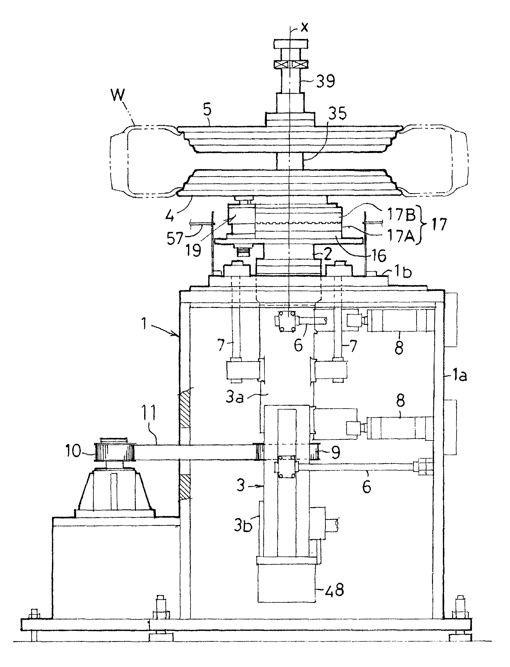
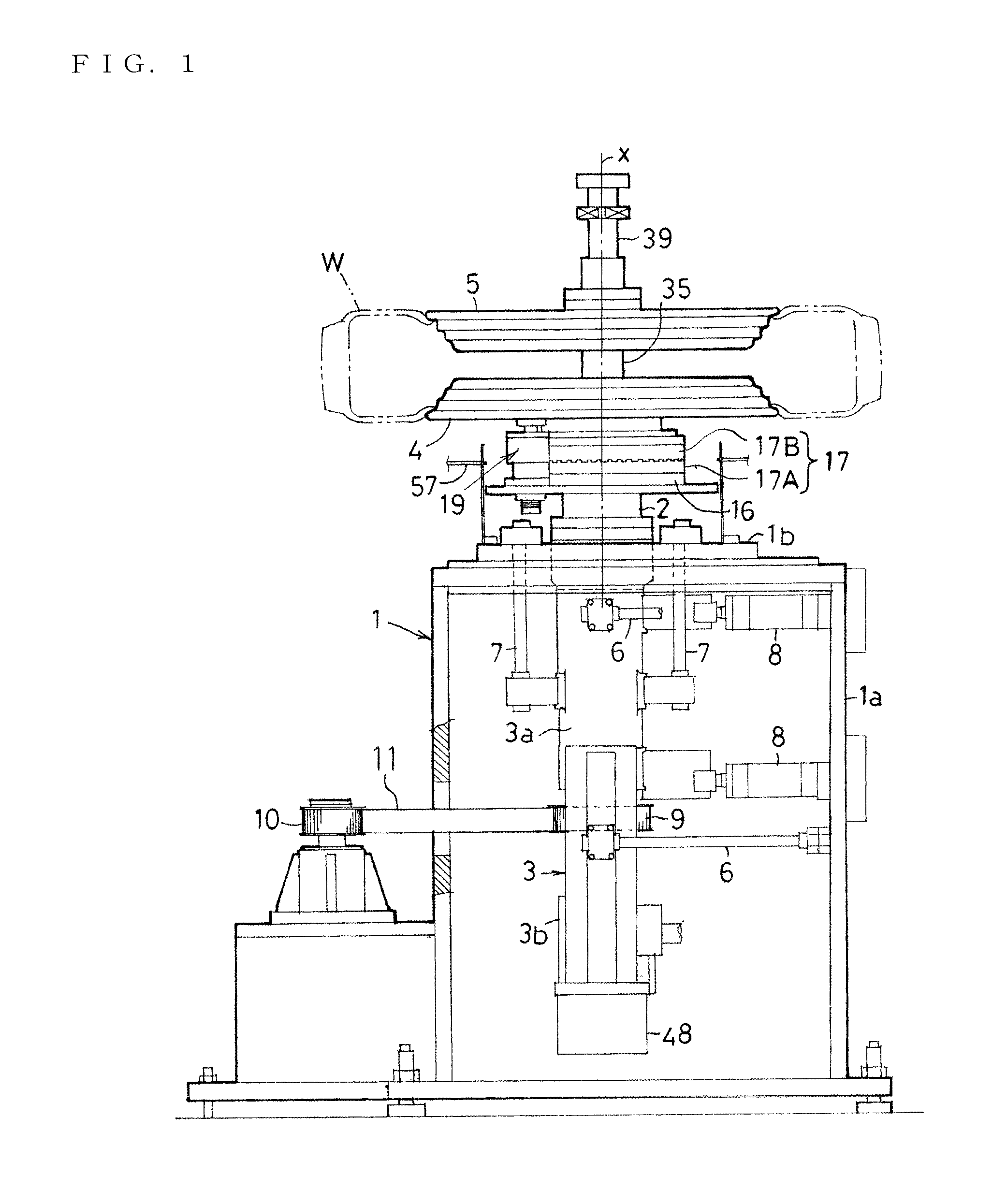
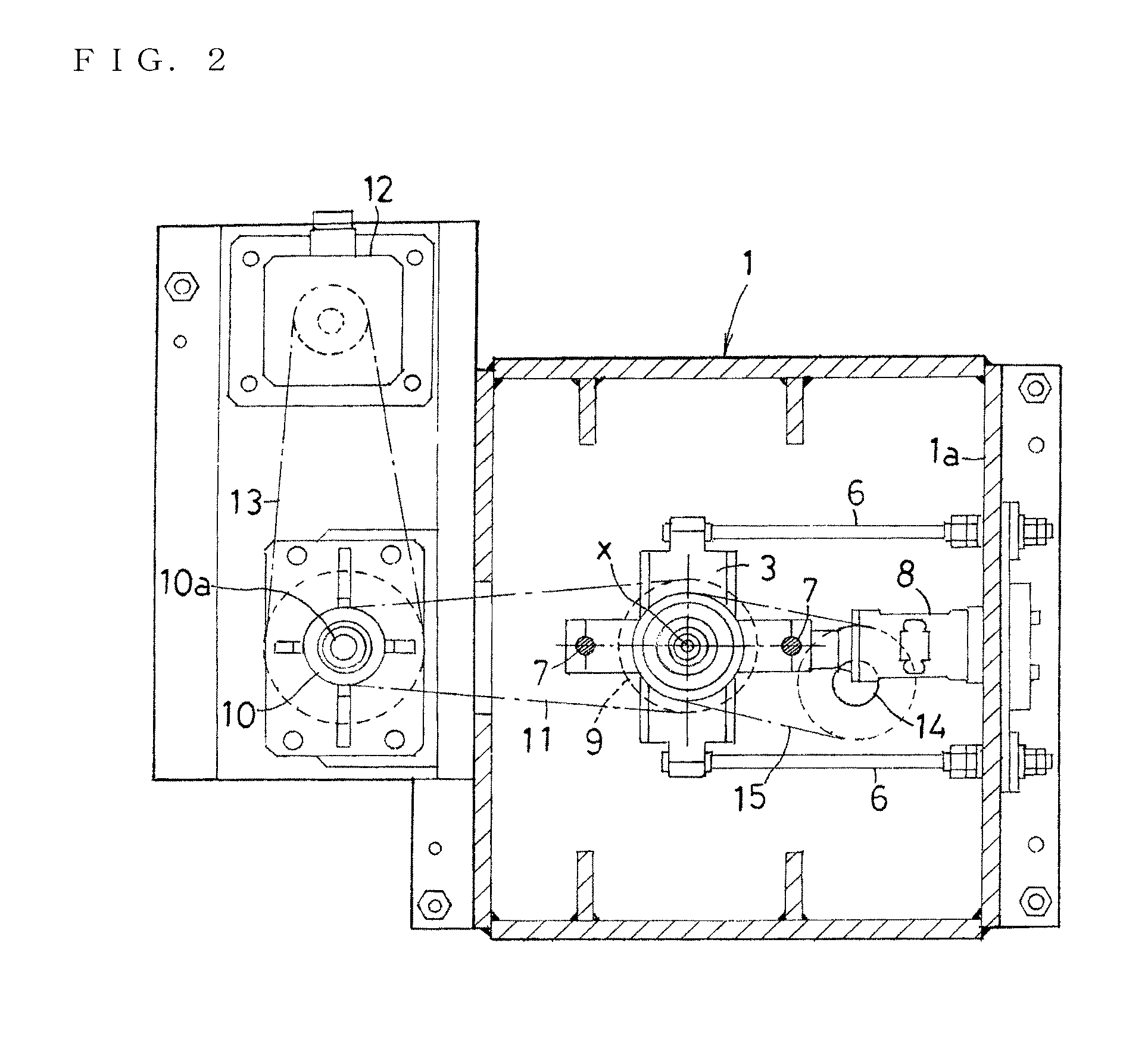
[0027]Hereinafter, an embodiment of the present invention will be described in detail with reference to the drawings. FIG. 1 shows a side view of a tire balance measurement apparatus of the embodiment of the present invention, FIG. 2 shows a cross sectional plan view of the apparatus, and FIG. 3 shows a vertically sectional front view of major parts of the apparatus. This tire balance measurement apparatus has a cylindrical support casing 3. The support casing 3 has a vertically-inserted and supported spindle 2. The support casing 3 is arranged in a center part of a main frame 1 fixed while standing. A lower rim 4 is coupled to an upper part of the spindle 2 protruding from an upper surface of the main frame 1. Further, an upper rim 5 facing the lower rim 4 while having a predetermined gap is arranged to be lifted and lowered.

[0028]In the tire balance measurement apparatus with the above configuration, after a tire W carried in a horizontal posture is fitted and loaded into the lowe...


PUM


Abstract

A lower side coupling of a Hirth coupling is coaxially coupled and fixed to a spindle, an upper side coupling of the Hirth coupling is coaxially coupled and fixed to a lower rim, the upper side coupling of the lower rim is meshed with the lower side coupling of the spindle, and upward separation of the lower rim from the spindle is prevented by chuck mechanisms.

Description

BACKGROUND OF THE INVENTION[0001]The present invention relates to a rim exchange device in a tire balance measurement apparatus.[0002]In a tire balance measurement apparatus (dynamic balancer) for measuring dynamic balance of a tire, after the tire to be subjected to measurement is carried and loaded into a lower rim coupled and fixed to a spindle, an upper rim standing by on the upper side is lowered by a lifting and lowering device, and the tire is nipped by the lower rim and the upper rim from the upper and lower sides. By charging the air into the tire to inflate the tire in this state and driving and rotating the spindle, the dynamic balance of the tire is measured (for example, refer to JP 8-15074 A).SUMMARY OF THE INVENTION[0003]In such a tire balance measurement apparatus, in a case where the size of the tire to be subjected to measurement is changed, there is a need for exchanging the upper and lower rims. Conventionally, the lower rim is coupled to the spindle by bolts. At...

Claims


Application Information

Patent Timeline
Patent Type & Authority Patents(United States)
IPC IPC(8): G01M17/013G01M17/02G01M1/16
CPCG01M17/021G01M1/16G01M17/02Y10T279/26
Inventor MIYAZAKI, SHINICHINAKAYAMA, KAZUOITO, TAKAAKI
Owner YAMATO SCALE CO LTD
Learn More