
Remote plasma source for controlling plasma skew

a plasma source and plasma technology, applied in the field of plasma processing systems and materials, can solve the problems of inability to achieve plasma uniformity targets, inconvenient plasma generation, and inconvenient process

Active Publication Date: 2016-10-11
APPLIED MATERIALS INC
View PDF20 Cites 113 Cited by
  • Summary
  • Abstract
  • Description
  • Claims
  • Application Information

AI Technical Summary

Benefits of technology

The patent text describes a plasma source for a plasma processing system that includes a core element and one or more coils. The plasma source also includes a plasma block with interior walls that encloses an annular plasma-generating volume. The plasma-generating volume has a first region that is symmetrical about perpendicular axes at a first point positioned along the first axis. The first region has a width in a direction parallel to the first axis and a depth in a direction perpendicular from the first axis. The width of the first region is at least three times greater than its depth. The plasma source also includes a second region further from the first axis than the first region is to the first axis. The technical effect of this design is to provide a plasma source that can generate a uniform plasma in the processing chamber, which is important for the quality and efficiency of plasma processing.

Problems solved by technology

However, sometimes it is not desirable or cost effective to generate a plasma in the chamber processing the substrate.
Although the open loop design has advantages, obtaining targets for plasma uniformity can be challenging.
When the plasma density is not centered or uniform across the horizontal direction relative to center of the annular plasma chamber, then the plasma-containing or radical containing gas will not be uniformly supplied to the process chamber, which creates non-uniformities in the process results achieved on the substrate being processed in the process chamber.

Method used


Image

  • Remote plasma source for controlling plasma skew
  • Remote plasma source for controlling plasma skew
  • Remote plasma source for controlling plasma skew

Examples


Embodiment Construction

[0020]Embodiments of the present disclosure generally provide a plasma source that is able to generate a uniform plasma within a plasma generation region of a plasma source and create a larger processing window in which to process a substrate, without significantly increasing processing or hardware costs.

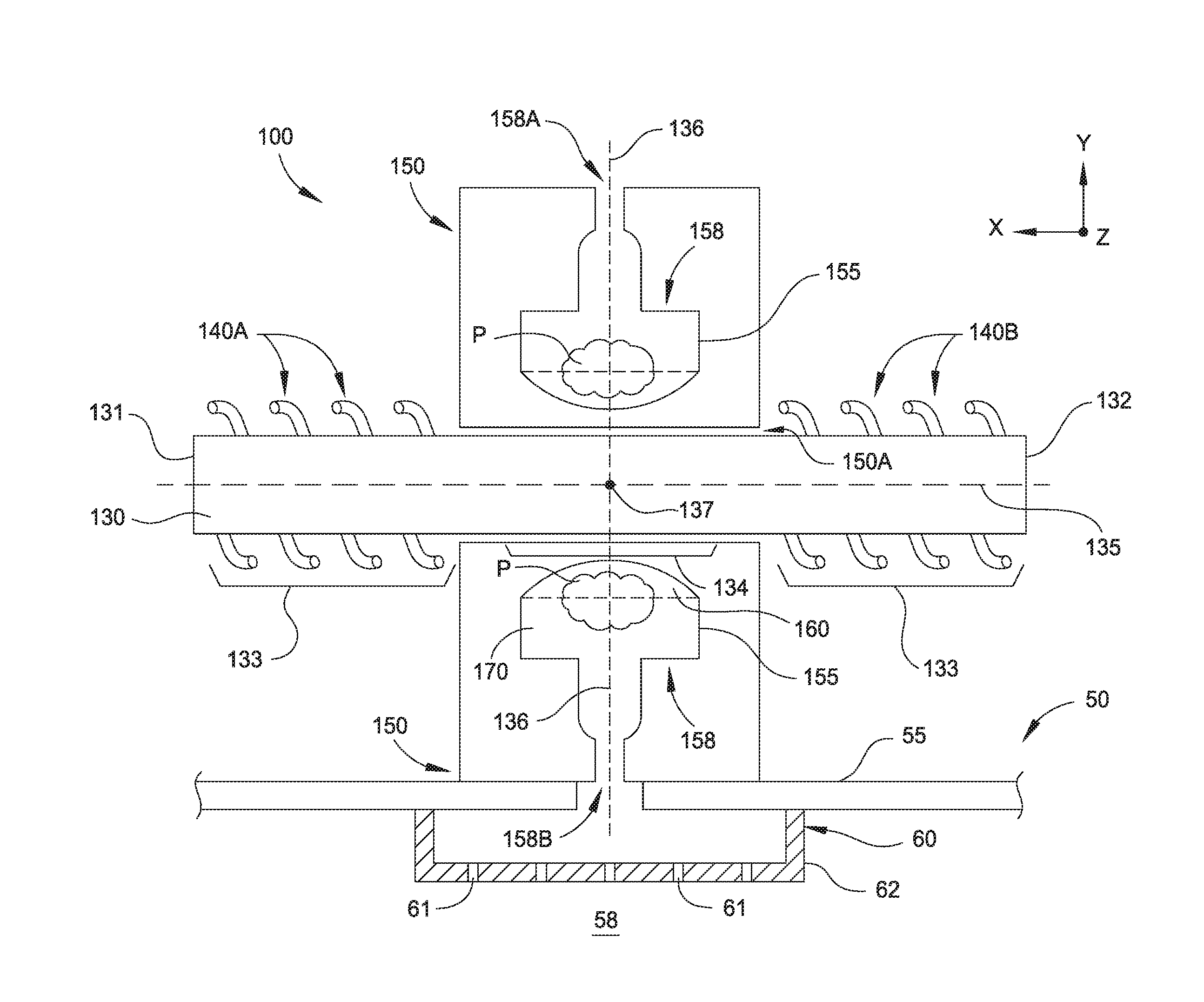
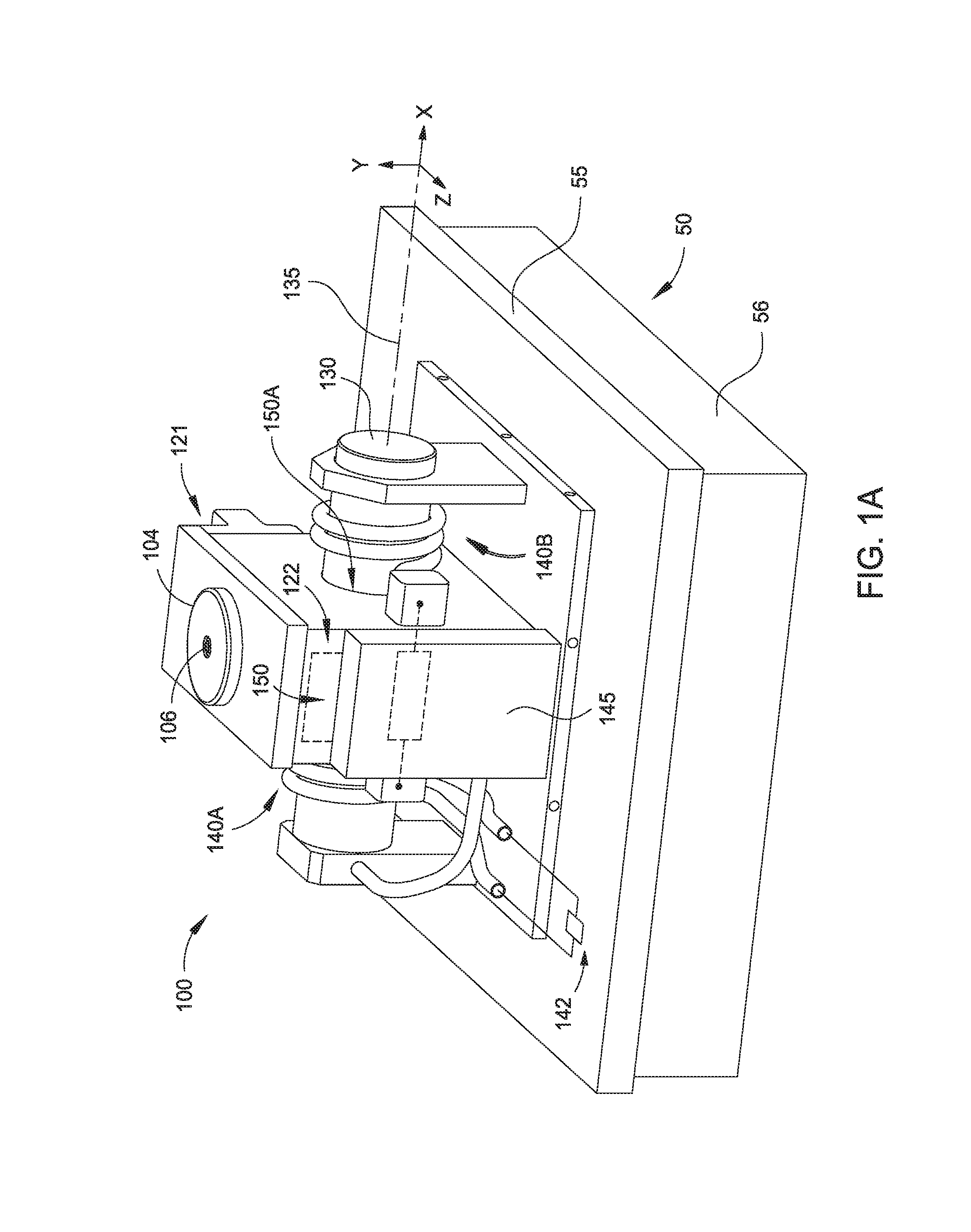
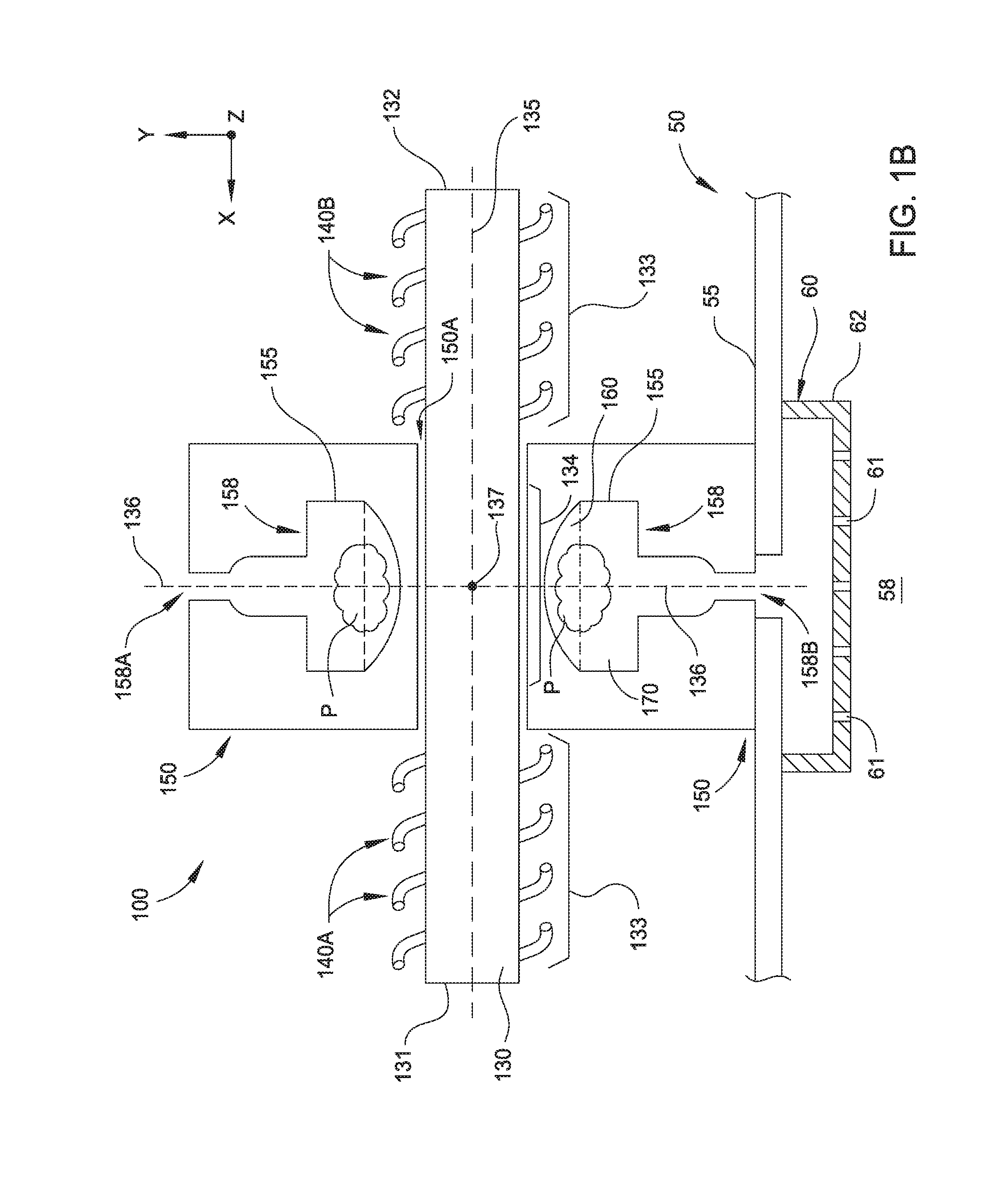
[0021]FIG. 1A is an isometric view of a plasma source 100 coupled to a process chamber 50, according to one embodiment. The plasma source 100 can be used to supply plasma containing radicals and / or ions to the process chamber 50. The process chamber 50 may include a chamber lid 55 and a chamber body 56 that enclose a processing region 58 (FIG. 1B) in which a substrate resides during processing. The plasma source 100 includes a dome portion 104 coupled to a plasma block 150. The plasma that is supplied to the process chamber 50 can be created in the plasma block 150. Gas that is used to form a plasma may be supplied to the annular plasma-generating volume 158 (FIG. 1B) of the plasma ...


PUM


Abstract

A plasma source is provided including a core element extending from a first end to a second end along a first axis. The plasma source further includes one or more coils disposed around respective one or more first portions of the core element. The plasma source further includes a plasma block having one or more interior walls at least partially enclosing an annular plasma-generating volume that is disposed around a second portion of the core element. The annular plasma-generating volume includes a first region that is symmetrical about a plurality of perpendicular axes that are perpendicular to a first point positioned on the first axis, the first region having a width in a direction parallel to the first axis and a depth in a direction perpendicular from the first axis. The first region has a width that is at least three times greater than the depth of the first region.

Description

CROSS-REFERENCE TO RELATED APPLICATIONS[0001]This application claims priority to U.S. Provisional Patent Application Ser. No. 62 / 133,160, filed on Mar. 13, 2015, which herein is incorporated by reference.BACKGROUND[0002]1. Field[0003]Embodiments disclosed herein generally relate to plasma processing systems and materials and apparatus for controlling plasma uniformity in plasma processing systems.[0004]2. Description of the Related Art[0005]Plasma processing chambers are regularly utilized in various electronic device fabrication processes, such as etching processes, chemical vapor deposition (CVD) processes, and other processes related to the manufacture of electronic devices on substrates. However, sometimes it is not desirable or cost effective to generate a plasma in the chamber processing the substrate. In such cases, a remote plasma source (RPS) can be used.[0006]Conventional RPS designs traditionally use a closed loop RF source configuration having windings that are wrapped a...

Claims


Application Information

Patent Timeline
Patent Type & Authority Patents(United States)
IPC IPC(8): H01J37/32
CPCH01J37/32458H01J37/3211H01J37/321H01J37/32568H01J2237/327H01J37/32357
Inventor KHAJA, ABDUL AZIZAYOUB, MOHAMAD A.BOKKA, RAMESHPINSON, II, JAY D.ROCHA-ALVAREZ, JUAN CARLOS
Owner APPLIED MATERIALS INC
Learn More