
Vehicle frame

a frame and vehicle technology, applied in the field of vehicle frames, can solve the problems of displacement of the sitting position of the driver towards the rear wheel, almost 100% of the weight is borne, and the negative spring travel is reduced, so as to achieve clear improvement in the frame setting, less compression of the damping element, and the effect of reducing the travel of the negative spring

Active Publication Date: 2016-10-18
CANYON BICYCLES
View PDF70 Cites 9 Cited by
  • Summary
  • Abstract
  • Description
  • Claims
  • Application Information

AI Technical Summary

Benefits of technology

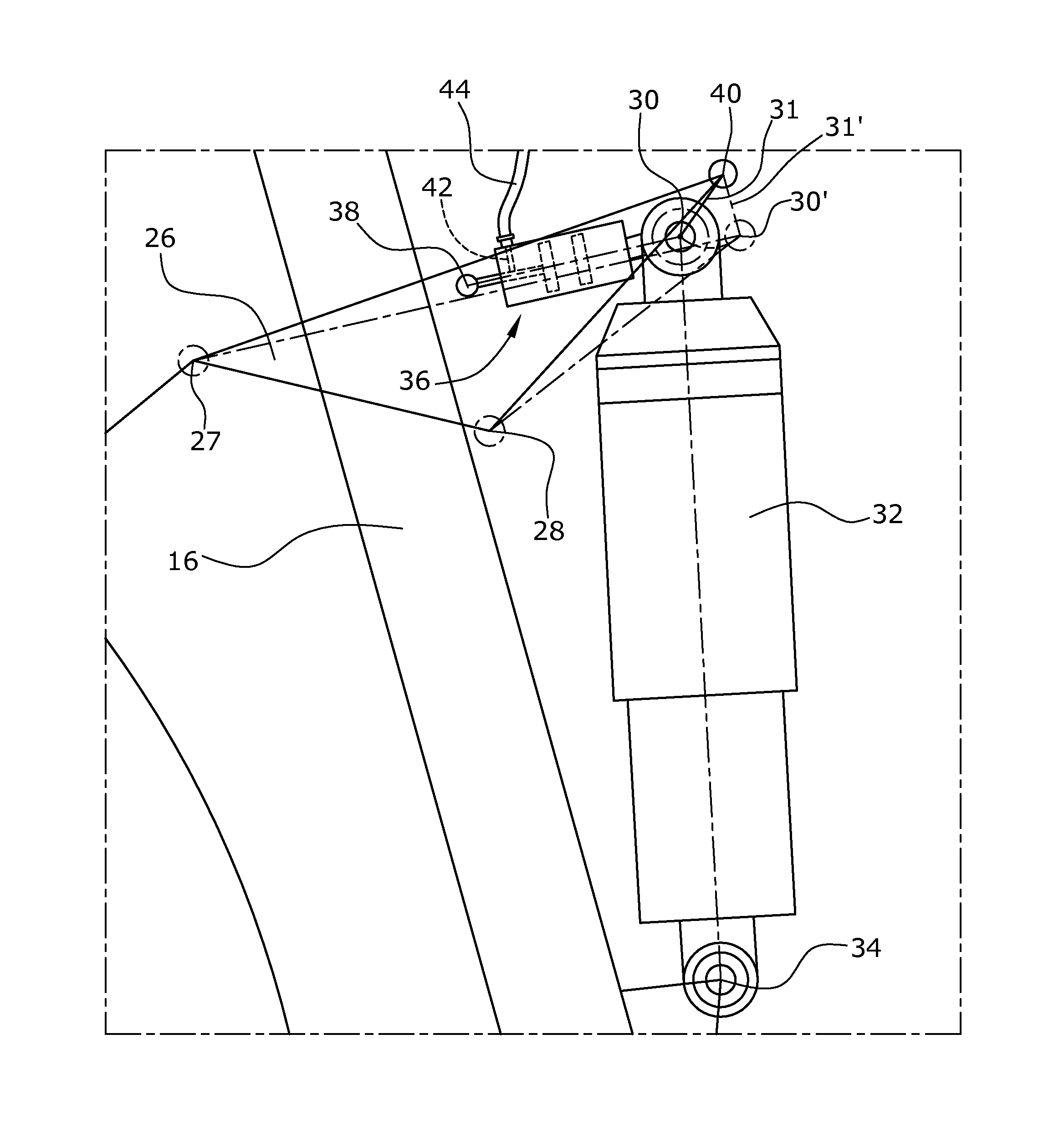
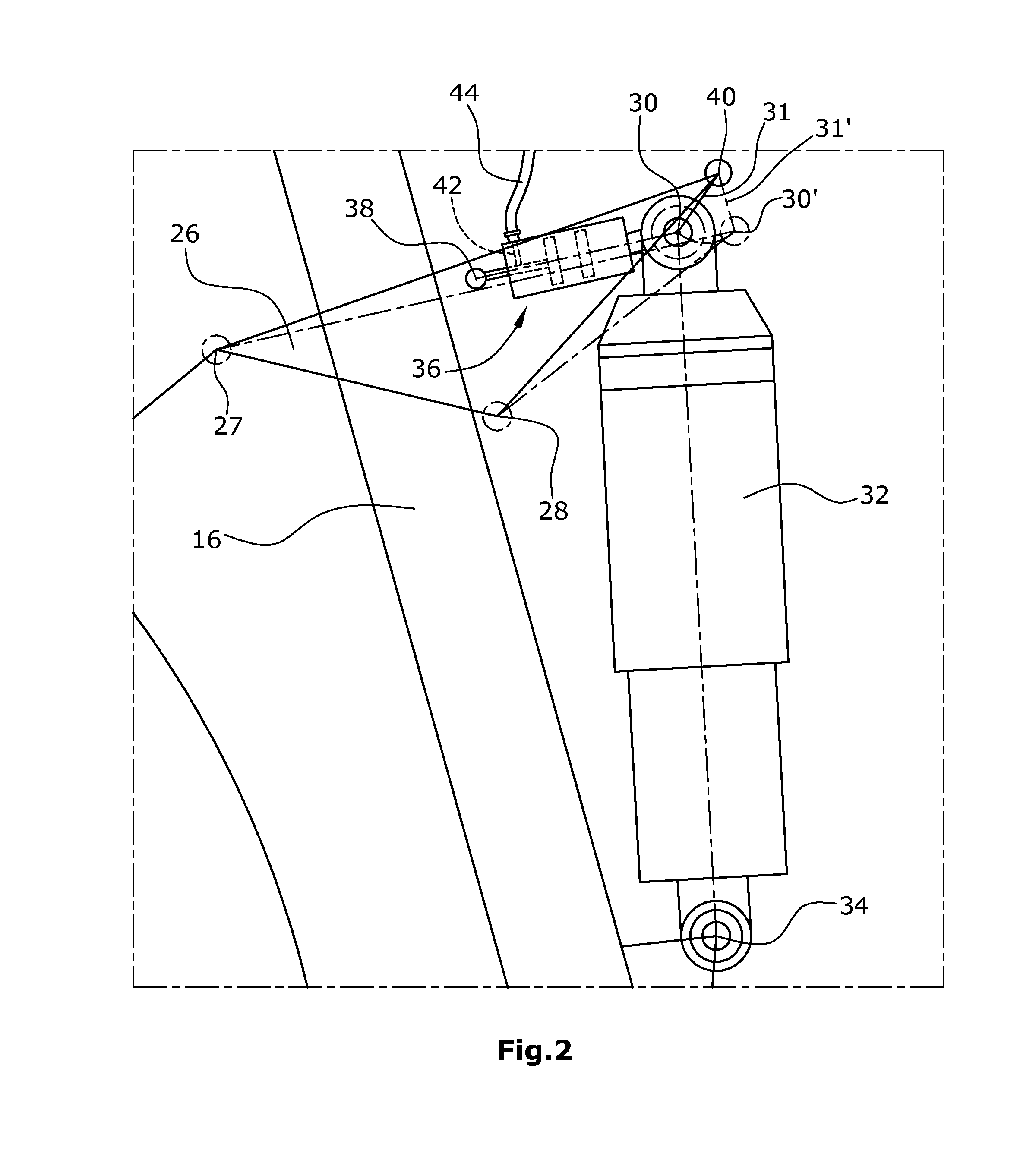
[0013]The damping element is connected with the main frame element, in particular with the seat tube of the main frame element, via a second connection point. The second connection point of the damping element may also be connected with the down tube or the top tube of the main frame element. Thus, the pivoting movement of the rear frame is dampened by the damping element during compression and, due to the adjustment of a negative spring travel, the damping element assists the rebound.
[0036]In a particularly preferred embodiment, the rear frame is directly connected with the main frame element via a main link bearing. Thus, the main link bearing is integrated in the main frame element or it is rigidly connected with the main frame element via an intermediate element. Thus, the main link bearing is preferably not moved when the displacing element is actuated. Therefore, the forces and moments introduced from the rear frame into the main frame element via the main link bearing do not have to be transmitted via an intermediate element. Thereby, the weight of the bicycle frame can be reduced considerably, in particular with respect to the configuration of the rear frame described in U.S. Pat. No. 7,712,757.

Problems solved by technology

Similarly, when riding down steep slopes, it may happen that almost 100% of the weight are borne by the front wheel so that a lift-off of the rear wheel may occur.
When riding uphill, such an adjustment of the negative spring travel results in an acute seat angle and thereby causes a displacement of the sitting position of the driver towards the rear wheel.
This causes the front wheel to lift off even at rather gentle ascending slopes.
Driving influences can be suppressed by adjusting the compression damping, whereby, however, energy is converted into heat so that the power of the driver is not fully used to move the bicycle.
Further, suppressing the driving influences does not cause a change in geometry so that the same is still unfavorable for riding uphill.
However, this means a considerable effort.
The dependence of the damping behavior on the chain tension is often perceived by cyclists as being objectionable.
Moreover, the solution described in U.S. Pat. No. 7,712,757 has the disadvantage that the overall weight of the frame is drastically increased thereby.
Thus, changing the position of the second connection point is rather troublesome and, in particular, is impossible to accomplish while riding.
Again, this is a frame geometry that can be changed only with effort using tools and, in particular, cannot be varied while riding.
In particular when riding uphill, this causes a rearward shifting of the sitting position and a frame setting unfavorable for riding uphill, in particular when the usual negative spring travel of 20-30% of the total spring travel has been set.
Likewise, opening the valve will result in the fluid flowing into this first fluid chamber and thus in the piston being pushed out.

Method used


Image

  • Vehicle frame
  • Vehicle frame
  • Vehicle frame

Examples


Embodiment Construction

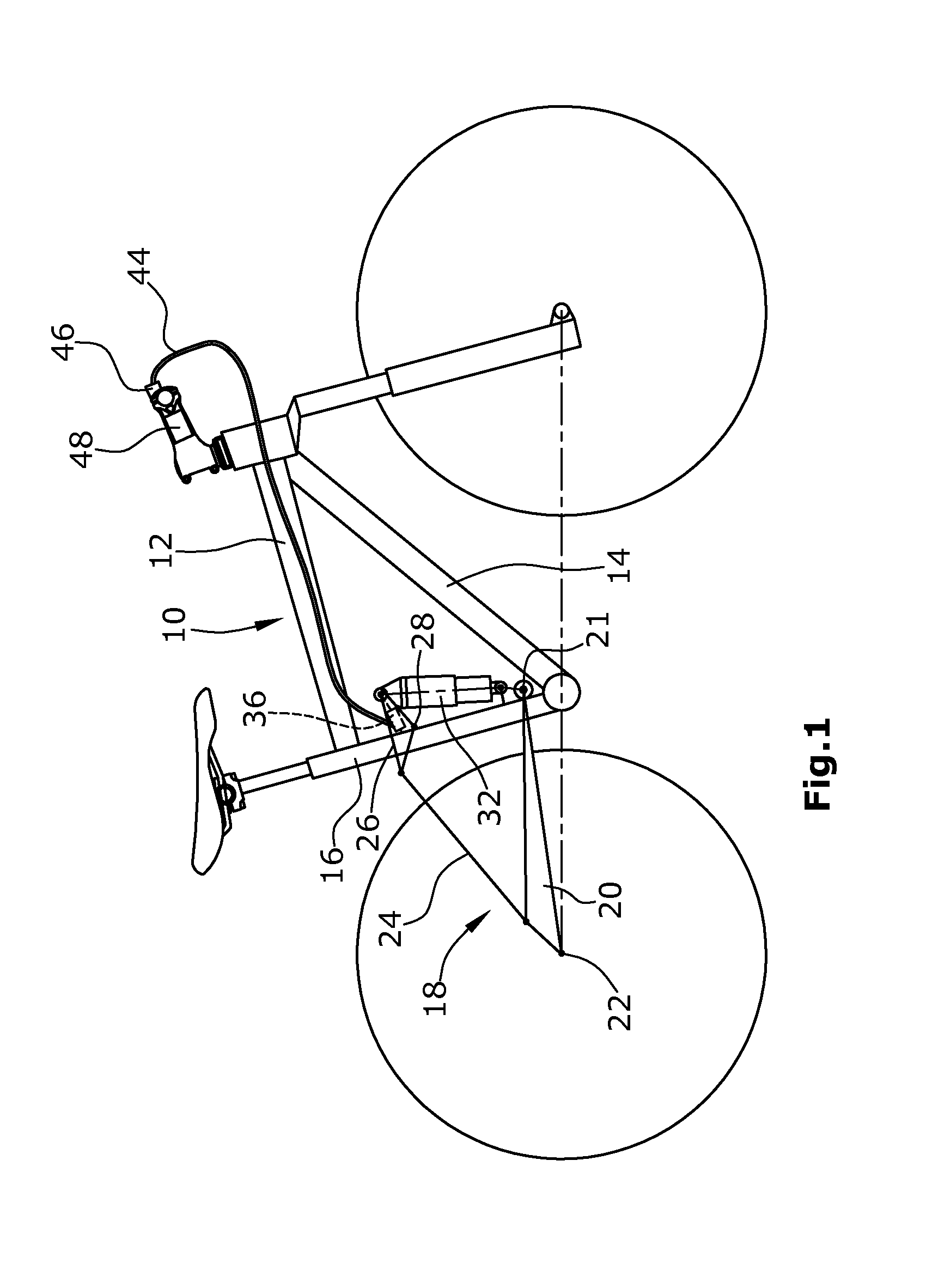
[0045]With reference to FIG. 1, a possible configuration of a main frame element, as well as of a rear frame will be described with reference to an example in connection with a damping element hinged thereto by means of a rocker link. Various possible configurations are illustrated in particular in FIGS. 6-11.

[0046]A mountain bike comprises a main frame element 10 which, in the embodiment illustrated, includes a top tube 12, a down tube 14 and a seat tube 16. The main frame element 10 is connected with a rear frame 18. The rear frame 18 has two chain stays 20 at the dropouts 22 of which the rear wheel axle. In this portion of the chain stays 20, two seat stays 24 are arranged that extend towards the seat tube 16. The seat stays 24 are connected with the dropouts of the chain stays 20 and, at a second hinge point 27, are pivotably connected with a rocker link 26 schematically illustrated as a triangle. The rocker link 26, schematically illustrated as a triangle in the Figures, is piv...


PUM


Abstract

A vehicle frame, in particular a mountain bike frame or a trekking bicycle frame, comprises main frame element. A rear frame is pivotably connected with the main frame element. A damping element is provided between the rear frame and the main frame element. A first connection point of the damper element is connected with the rear frame and a second connection point of the damping element is connected with the main frame element. For the purpose of changing the frame characteristics, a displacing element is provided for the displacement of the first connection point. The locking of the displacing element is done with the help of an actuator element.

Description

BACKGROUND[0001]1. Field of the Disclosure[0002]The disclosure relates to a vehicle frame, in particular to a bicycle frame for mountain bikes or trekking bicycles.[0003]2. Discussion of the Background Art[0004]In particular with bicycles used under riding conditions that vary extremely, such as mountain bikes or trekking bicycles, it is common to provide a sprung rear frame, i.e. a rear frame that is pivotably connected with a main frame element. With such a frame, the main frame element is formed by a top tube, a down tube and a seat tube, while other frame geometries are conceivable. Under varying riding conditions, ranging from steep downhill slopes to steep uphill slopes, the load distribution between the front wheel and the rear wheel changes drastically. When riding on plane ground, about 70% of the weight force act on the rear wheel and only 30% act on the front wheel. On the other hand, when riding uphill, almost 100% of the weight act on the rear wheel so that the front wh...

Claims


Application Information

Patent Timeline
Patent Type & Authority Patents(United States)
IPC IPC(8): B62K1/00B62K25/12B62K25/28B62K25/04
CPCB62K25/12B62K25/28B62K25/286B62K2025/048
Inventor THOMA, VINCENZ
Owner CANYON BICYCLES
Learn More