
Solar light

a solar energy and solar energy technology, applied in the field of solar energy, can solve the problems of incontestable effectiveness of illuminated signs versus unlit signs, inconvenient and deleterious night navigation for navigators, and new set of problems for navigators

Inactive Publication Date: 2016-10-18
AFMODEL LLC
View PDF23 Cites 7 Cited by
  • Summary
  • Abstract
  • Description
  • Claims
  • Application Information

AI Technical Summary

Benefits of technology

The invention is a mounting system for a light illuminating device on a vessel. The system includes a base and two mounting legs: one vertical and one horizontal. A L-shaped mounting channel is defined between the first mounting leg, the base, and the second mounting leg for abutting the vertical freeboard portion and the horizontal deck portion respectively. A deformable bumper extends from the base for cushioning and distancing the vessel from water platform. The bumper has a bulbous body portion with a bulbous depth and a taper body portion with a taper depth. The cantilever protects the light illuminating device upon the vessel contacting the bulbous body portion. The technical effect of this invention is to provide a secure and flexible mounting system for a light illuminating device on a vessel, which can withstand impact and distortion during use.

Problems solved by technology

Night navigation presents a new set of problems for the navigator.
Although the dayboards contain highly reflective coatings to enable a navigator to identify them, the need to frequently shine a light to illuminate the ATON is both inconvenient and deleterious to the night vision of the navigator.
The effectiveness of an illuminated sign versus an unlit sign is undisputable.
None, however completely satisfies the requirements for a complete solution to the aforestated problem.
Therefore, the name plate is illuminated when insufficient ambient light is available.
Although the aforementioned prior art have contributed to the development of the art illuminating signs and the like, none of these prior art patents have solved the needs of this art.

Method used


Image

  • Solar light
  • Solar light
  • Solar light

Examples


first embodiment

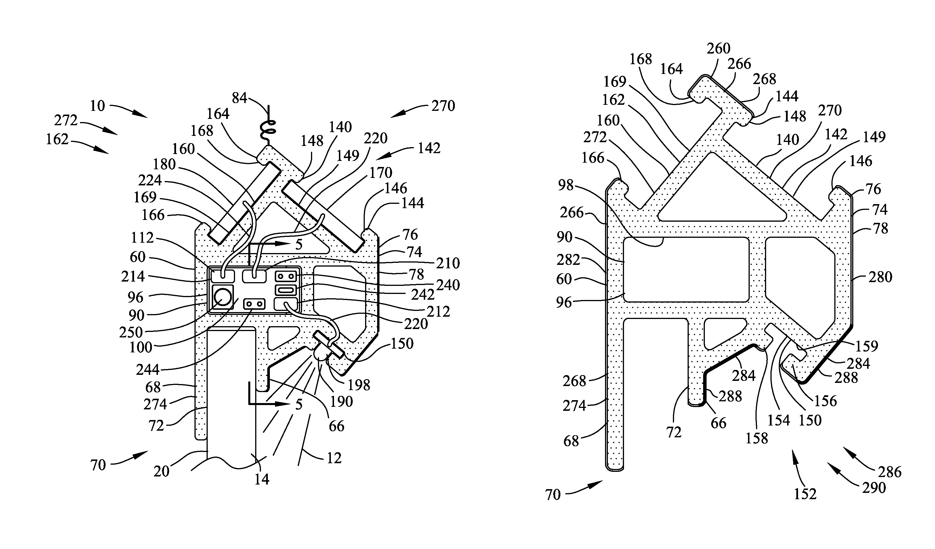
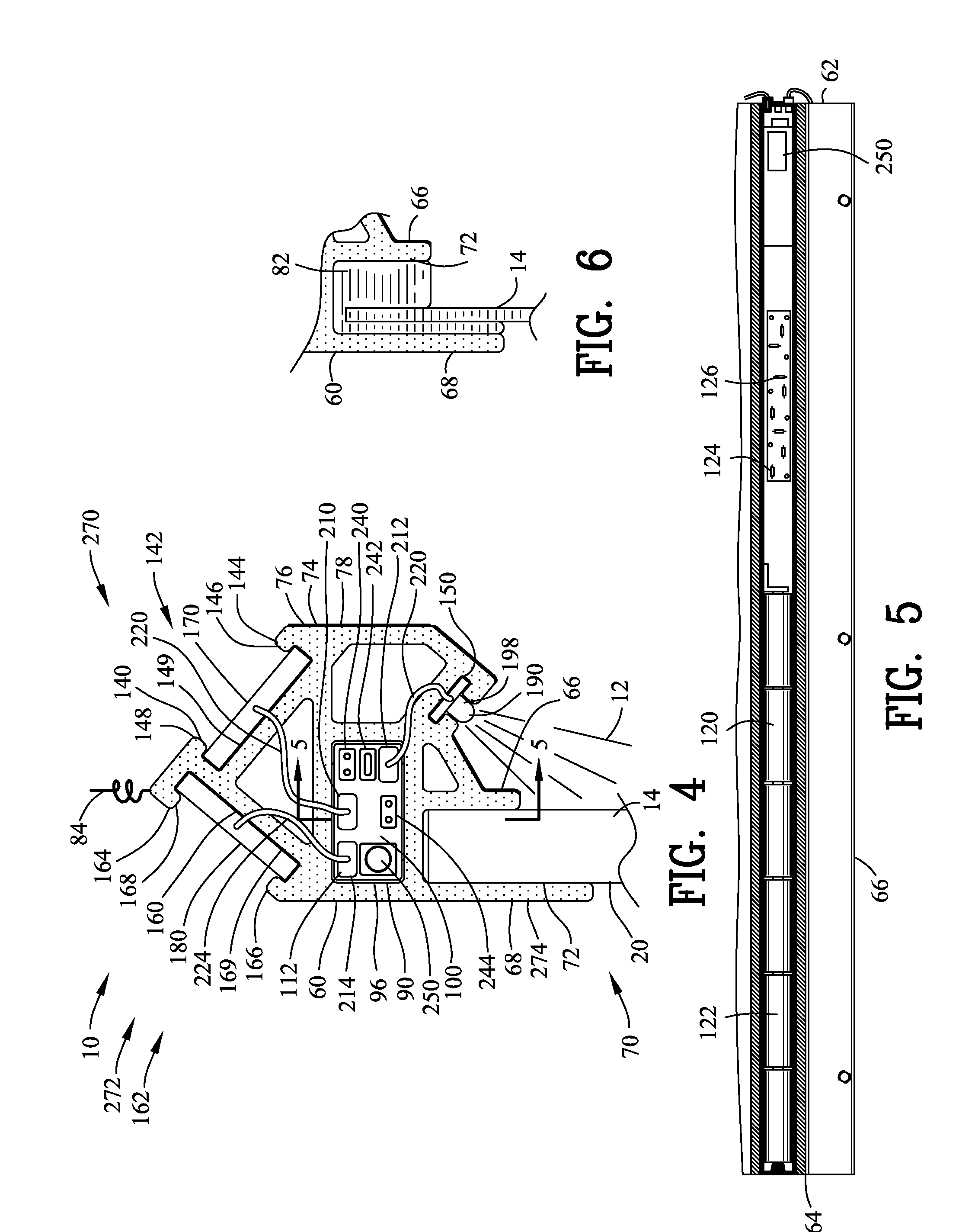
[0091]Specifically to the first embodiment in FIGS. 1-8, 13 and 15, the upper track 140 defines an offset orientation 170 relative to the mounting channel 72. Furthermore, the second upper track 160 defines a non-offset orientation 272 relative to the mounting channel 72. The offset orientation 170 in combination with the non-offset orientation to 72 permits the installation of the illuminating device 10 wherein the clearance adjacent to the second mounting leg 68 is severely restricted. More specifically, the illuminating device 10 in FIGS. 1-8, 13 and 15 provides for a generally linear edge along the second mounting leg 68.

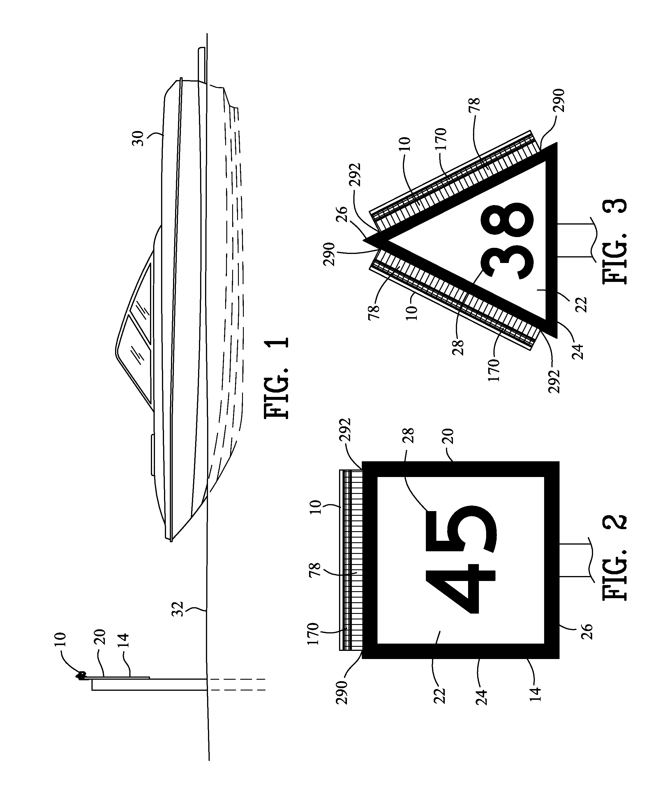
[0092]As best shown in FIGS. 2 and 3, the channel marker 20 has an interior color 22 and a border color 24. The border color 24 has a border width 26. As best shown in FIGS. 1-4 and 15, the base 60 includes a front side 280 and a rear side 282. The front side 280 has a border portion height 284. The border portion height 284 is equivalent to the border width 26 ...

second embodiment

[0095]Specifically to the second embodiment in FIGS. 10-12, 14 and 16, the second upper track defines a second offset orientation 300 relative to the mounting channel 72. The upper track 140 and the second upper track 160 define opposite orientations. More specifically, the first offset orientation 270 and the second offset orientation 300 are equivalent for defining a symmetrical cross-section 304 in the base 60.

[0096]In addition, the second embodiment includes a second lower track 310 coupled to the base 60 and has a generally descending orientation 312. Preferably, second lower track 310 defining a generally C-shape cross-section 314. More specifically, the general C-shape cross-section 314 of the second lower track 310 includes a primary arm 316 and a secondary arm 318 that is coupled by a track wall 149.

[0097]A second light illuminating device 320 is removably engaged within the second lower track 310. The second light illuminating device 320 preferably has an elongated configu...

third embodiment

[0103]FIGS. 17-24 illustrate the subject invention. In FIGS. 17-24 the illuminating device 10 illuminates a water platform 400, a body of water 32, and / or a vessel 30 located adjacent to the water platform 400. The water platform 400 may include a floating dock 402, a vertical column supported dock 402, or other objects positioned on, above and / or adjacent to a body of water 32. The water platform 400 may include a horizontal deck portion 404 and a vertical freeboard portion 406. The vessel 30 may be positioned adjacent to the water platform 400 for docking.

[0104]Similar to FIGS. 1-16, the illuminating device 10 in FIGS. 17-24 includes a base 60 extending between a proximal end 62 and a distal end 64. FIGS. 17-24 include a first mounting leg 410 extending from the base 60 in a generally vertical orientation 412. A second mounting leg 414 extends from the base 60 in a generally horizontal orientation 416. A L-shaped mounting channel 420 defined between the first mounting leg 410, the...


PUM


Abstract

An illuminating device is disclosed for projecting an electromagnetic radiation. The device includes a base having a first mounting leg and a second mounting leg extending in any generally descending orientation. The first mounting leg and the second mounting leg are positioned on opposing sides of an object. The base removably engages with a power source, a solar panel and a light illuminating. The light illuminating device projects an electromagnetic radiation in a generally descending orientation.

Description

CROSS-REFERENCE TO RELATED APPLICATIONS[0001]This application claims benefit of U.S. Patent Provisional application No. 62 / 031,262 filed Jul. 31, 2014. All subject matter set forth in provisional application No. 62 / 031,262 is hereby incorporated by reference into the present application as if fully set forth herein.[0002]This application claims benefit of U.S. Patent Provisional application No. 62 / 135,634 filed Mar. 19, 2015. All subject matter set forth in provisional application No. 62 / 135,634 is hereby incorporated by reference into the present application as if fully set forth herein.BACKGROUND OF THE INVENTION[0003]1. Field of the Invention[0004]This invention relates to illuminating devices and more particularly to a solar light.[0005]2. Background of the Invention[0006]Aids to Navigation (ATONS) comprise floating and fixed channel markers which may be lit or unlit to aid a vessel operator in safely transiting waterways. For daytime navigation, ATONS bear numerical, color and ...

Claims


Application Information

Patent Timeline
Patent Type & Authority Patents(United States)
IPC IPC(8): F21S8/00B63B45/04F21V23/04F21S9/03F21S4/00F21V19/00F21V23/00B63B59/02F21S10/00F21V33/00F21W111/04F21W111/047F21Y103/00
CPCF21S10/002B63B59/02B63B45/04F21V33/0064F21S9/037F21S4/008F21S8/03F21V19/0015F21V23/001F21V23/0464F21W2111/047F21W2111/04F21Y2103/003F21V21/08F21Y2113/00F21S4/28F21Y2103/10G09F13/02G09F2013/222F21Y2115/10
Inventor PLOUCHER, RAYMOND A.GILMORE, MICHAEL
Owner AFMODEL LLC
Learn More