Axial flow turbine
a flow turbine and axial flow technology, applied in the direction of machines/engines, gas turbine plants, stators, etc., can solve the problems of increasing friction loss, insufficient etc., to reduce the circumferential velocity component, and enhance the effect of reducing mixing loss
- Summary
- Abstract
- Description
- Claims
- Application Information
AI Technical Summary
Benefits of technology
Problems solved by technology
Method used
Image
Examples
first embodiment
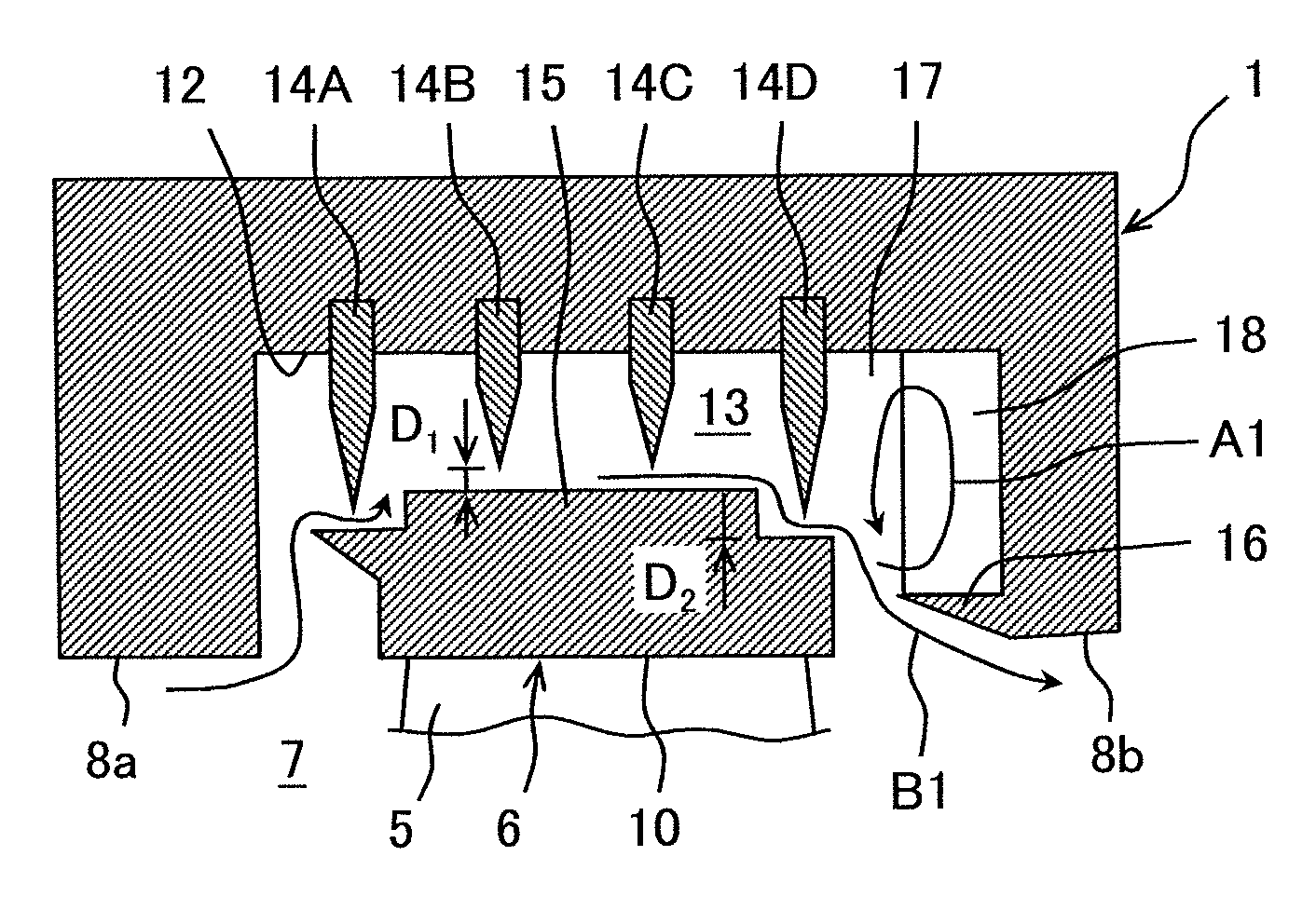
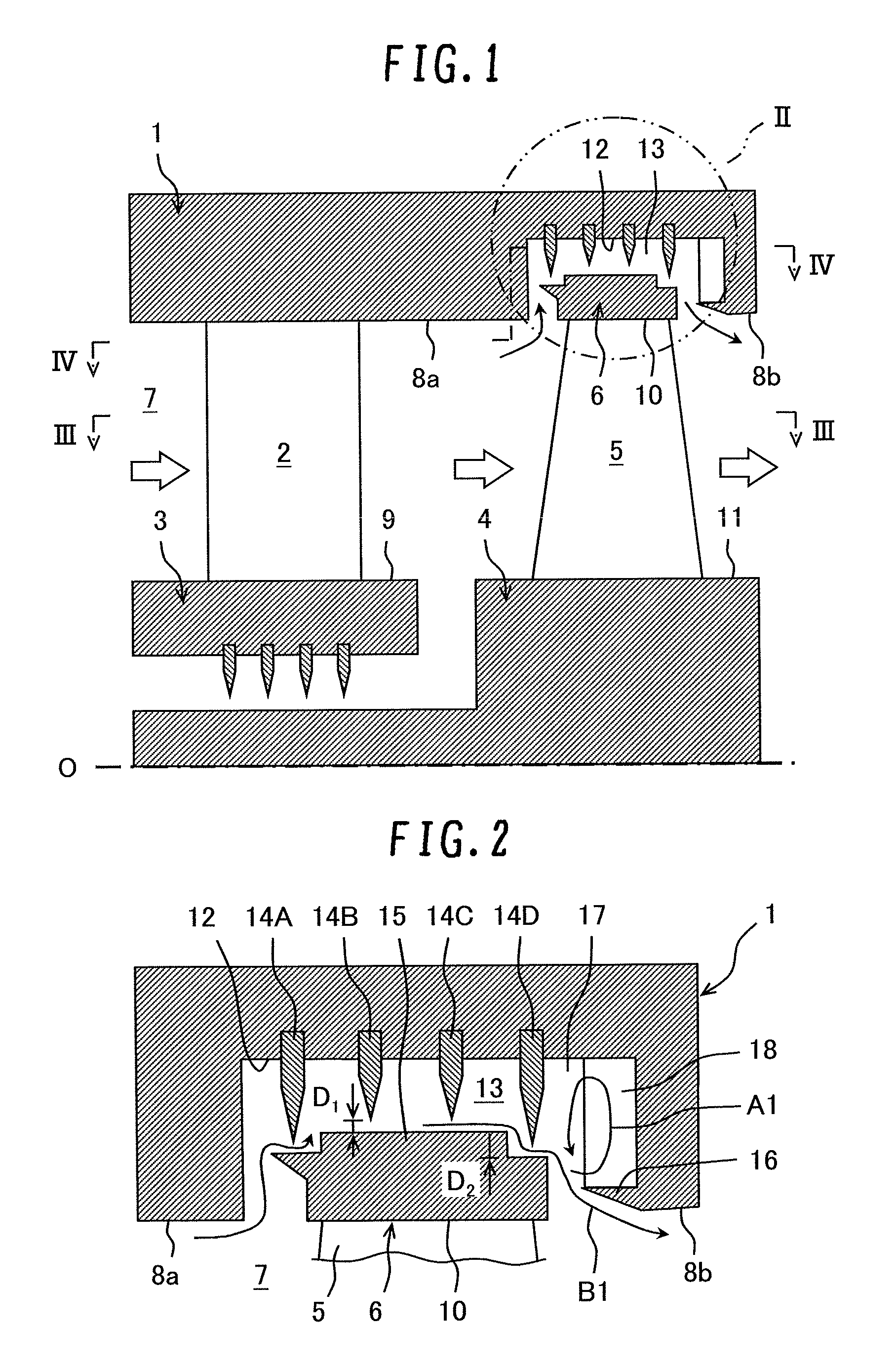
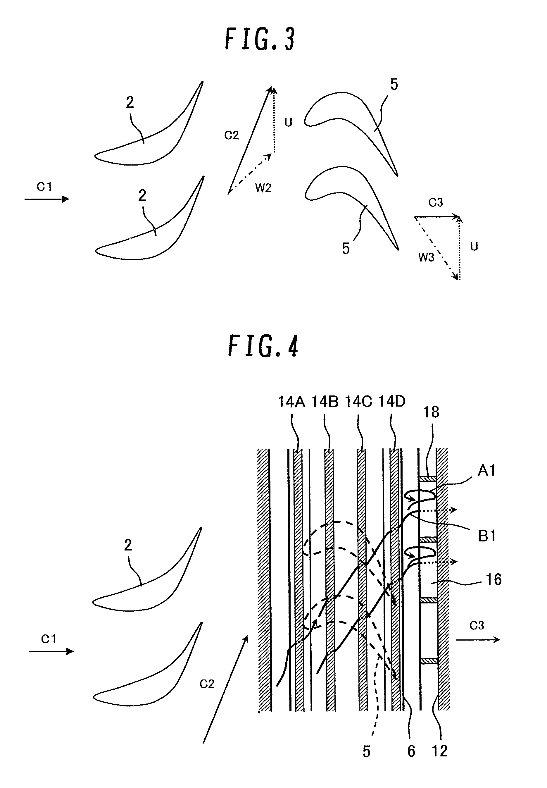
[0030]FIG. 1 is a schematic cross-sectional view of a partial structure (a stage structure) of a steam turbine as viewed in a rotor-axial direction according to the present invention. FIG. 2 is a partial enlarged cross-sectional view of a II-part in FIG. 1, illustrating a detailed structure of a clearance passage. FIG. 3 is a cross-sectional view as viewed in a rotor-circumferential direction taken along line III-III in FIG. 1, illustrating a flow in a main passage. FIG. 4 is a cross-sectional view as viewed in the rotor-circumferential direction taken along line IV-IV, illustrating a flow in the clearance passage together with the flow in the main passage.
[0031]Referring to FIGS. 1 to 4, a steam turbine includes an annular diaphragm outer ring 1 (a stationary body) provided on the inner circumferential side of a casing (not shown), a plurality of stator blades 2 provided on the inner circumferential side of the diaphragm outer ring 1, and an annular diaphragm inner ring 3 provided ...
second embodiment
[0058]the present invention is described with reference to FIG. 9. In the present embodiment the same portions as those in the above first embodiment are denoted by like reference numerals and their explanations are arbitrarily omitted.
[0059]FIG. 9 illustrates a detailed structure of a clearance passage according to the second embodiment.
[0060]In the present embodiment, a cutout is formed in the downstream side end portion of a shroud 6C. Specifically, the shroud 6C has an outer circumferential surface 21a to which a final-stage seal fin 14D is opposed, an outer circumferential surface 21b which is located on the rotor-radial outside (the upside in the figure) of the outer circumferential surface 21a and to which the seal fin 14C anterior to the final stage seal fin is opposed, and a stepped lateral surface 22 formed between the outer circumferential surface 21a and the outer circumferential surface 21b.
[0061]A clearance dimension D1 between the tip of each seal fin and the outer c...
PUM
 Abstract
Description
Claims
Application Information
 - R&D
- Intellectual Property
- Life Sciences
- Materials
- Tech Scout
- Unparalleled Data Quality
- Higher Quality Content
- 60% Fewer Hallucinations
Browse by: Latest US Patents, China's latest patents, Technical Efficacy Thesaurus, Application Domain, Technology Topic, Popular Technical Reports.
© 2025 PatSnap. All rights reserved.Legal|Privacy policy|Modern Slavery Act Transparency Statement|Sitemap|About US| Contact US: help@patsnap.com


