Portable load-breaking and pickup jumper apparatus

a load-breaking and load-jumping technology, applied in the field of power distribution service and maintenance industries, can solve the problems of dangerous electric arcing, dangerous maintenance and repair work on overhead power lines, and cut power to all customers downstream of the switch, so as to achieve the effect of mitigating dangerous arcing

Active Publication Date: 2016-10-25
UTILITY SOLUTIONS
View PDF6 Cites 1 Cited by
  • Summary
  • Abstract
  • Description
  • Claims
  • Application Information

AI Technical Summary

Benefits of technology

[0006]These and other shortcomings of the prior art are addressed by the present invention, which provides a portable load-breaking and pickup jumper apparatus configured for controlled closing to mitigate dangerous arcing.

Problems solved by technology

Unfortunately, maintenance and repair work on overhead power lines can be quite dangerous.
For example, cutting live power cables can result in dangerous electric arcing.
However, opening an upstream switch associated with the power line cuts power to all customers downstream of the switch.
That being said, present day devices do not control arcing in a manner suitable for high amperage situations.

Method used


Image

  • Portable load-breaking and pickup jumper apparatus
  • Portable load-breaking and pickup jumper apparatus
  • Portable load-breaking and pickup jumper apparatus

Examples


Embodiment Construction

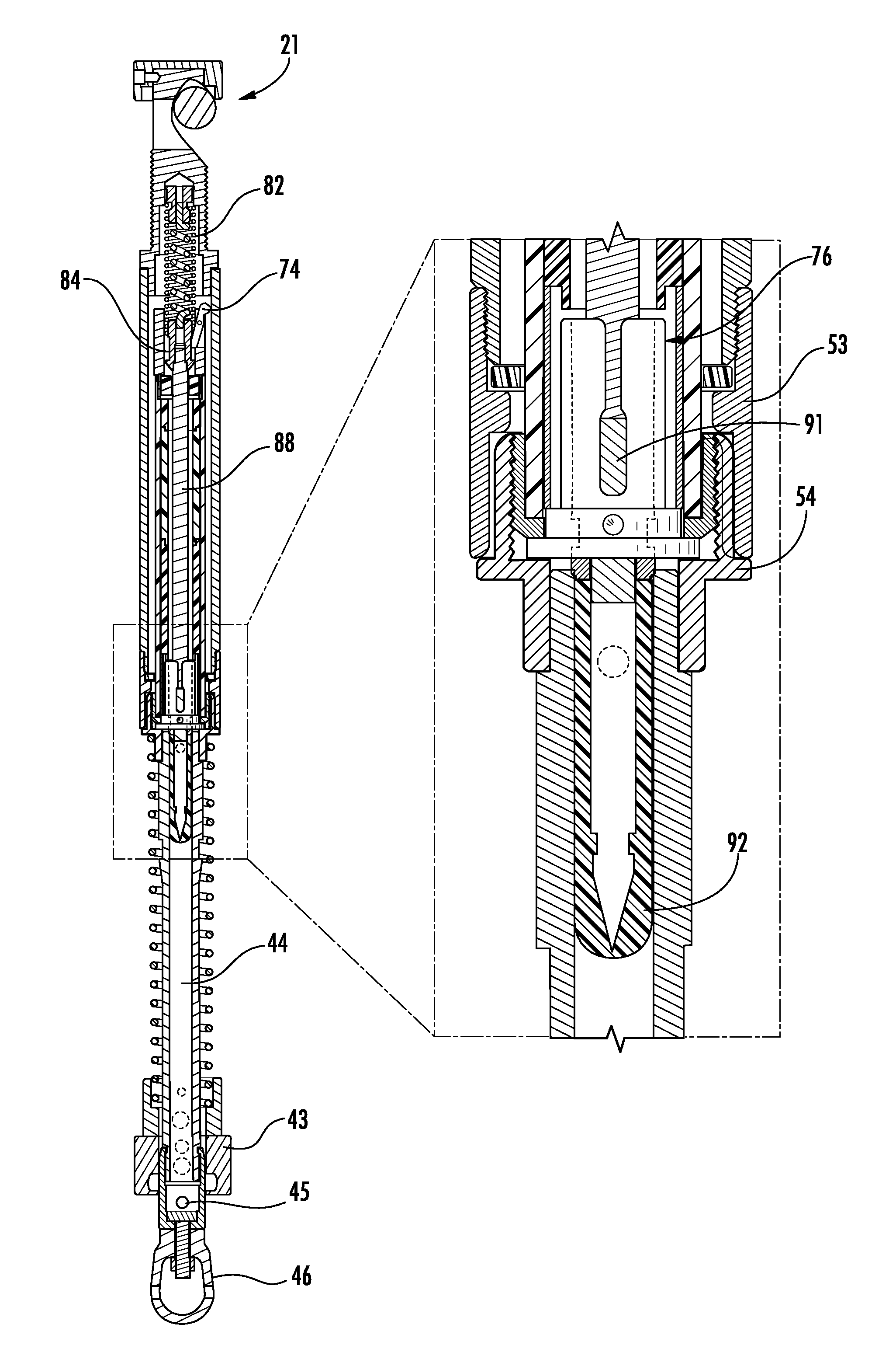
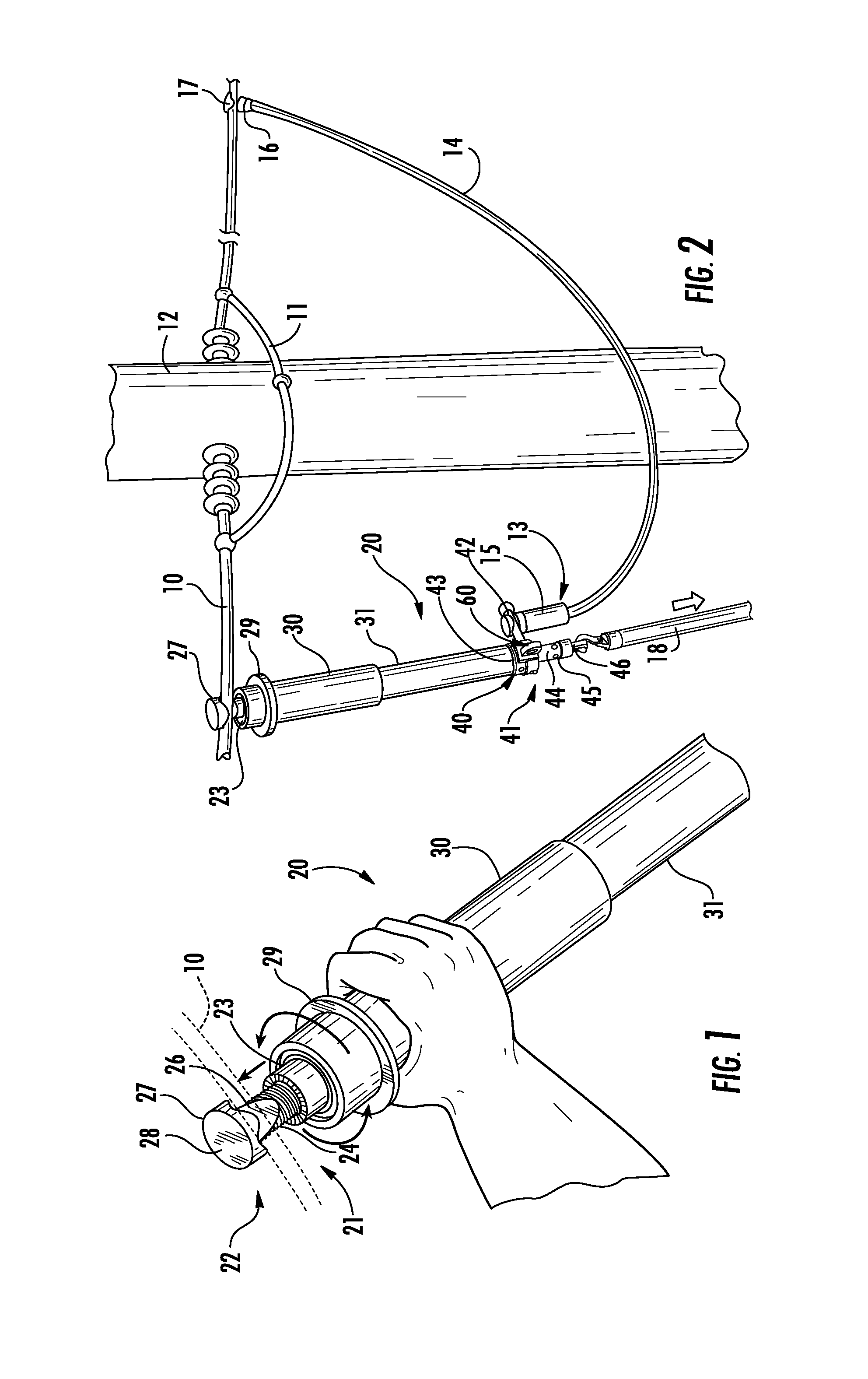
[0019]Referring to the drawings, an exemplary portable load breaking and pickup jumper apparatus according to the present invention is illustrated in FIGS. 1-3 and shown generally at reference numeral 20. The apparatus 20 is designed to be placed onto a power line 10 to quickly break and return a load to portions of the line 10.

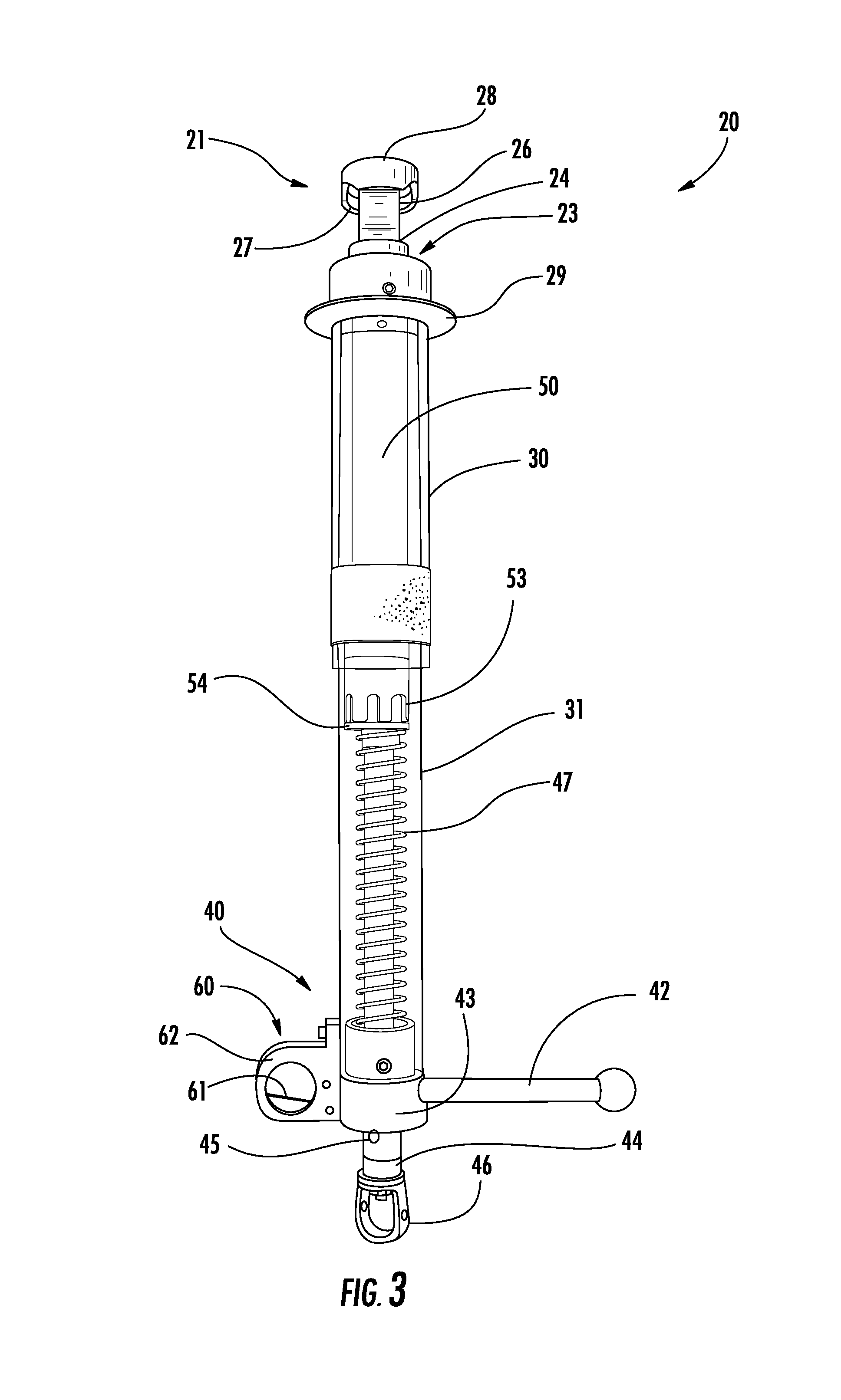
[0020]The apparatus 20 typically includes a first connector 21 positioned at a first end 22 of the apparatus 20 for direct connection to the power line 10 and a second connector 40 positioned on a second end 41 of the apparatus 20 to allow a jumper cable 14 to be connected between the connector 40 and the power line 10.

[0021]The first connector 21 and second connector 40 are formed from one or more conductive materials. The first connector 21 includes a clamp head 23, a threaded clamp body 24 having a clamping surface 26 (i.e., cut away or grooved portion) and a hook portion 27, and a top cap 28 connected to the threaded clamp body 24. The clamp head 23 inclu...


PUM


Abstract

A portable load-breaking and pickup apparatus for handling a load associated with a power distribution system is disclosed. The apparatus includes first and second spaced-apart connectors electrically connected by a load break assembly. The load break assembly includes first and second outer contacts configured for mating engagement and configured to provide a low-resistance path between the first and second connectors, and first and second inner contacts configured for mating engagement and configured to provide a high-resistance path between the first and second connectors. The load break assembly transitions from an open position to a closed position in two stages. The two stages include closing the high-resistance path prior to closing the low-resistance path, and closing the low-resistance path after the high-resistance path has been closed.

Description

BACKGROUND OF THE INVENTION[0001]The present invention relates to the field of the power distribution servicing and maintenance industries and, more particularly, to an apparatus for handling a load associated with a power distribution system.[0002]Over the years, power distribution systems have been developed which distribute power from various types of power generation facilities to end users such as residential and commercial customers. Today, power is still primarily distributed to residential and commercial customers using overhead-power-line networks. As used herein, an upstream direction along a power line will generally be in a direction toward a power generation facility or power source, and a downstream direction along a power line will generally be in a direction toward a customer, e.g., residential or commercial, or other user of power.[0003]These overhead-power-line networks require regular maintenance and repair to ensure proper operation, thereby ensuring that custome...

Claims


Application Information

Patent Timeline
Patent Type & Authority Patents(United States)
IPC IPC(8): H01H31/00H01H33/16H02G1/02
CPCH01H31/00H01H33/16H02G1/02H01H31/006
Inventor WOOD, EUGENE H.NOLTE, MATTHEW G.
Owner UTILITY SOLUTIONS
Why Eureka
Try Eureka