Self-conforming plates for capacitive machines such as electrostatic motors and generators

a capacitive machine and self-conform technology, applied in the field of capacitive machines, can solve the problems of limited plate spacing and parallel alignment, low power density, and presently rarely used capacitive machines

Active Publication Date: 2016-10-25
C MOTIVE TECHNOLOGIES INC
View PDF17 Cites 11 Cited by
  • Summary
  • Abstract
  • Description
  • Claims
  • Application Information

AI Technical Summary

Problems solved by technology

Despite the foregoing, capacitive machines are presently rarely used.
This is in large part owing to the relatively low capacitive coupling that can practically be obtained between the moving and stationary plates of practical capacitive machines, resulting in low power density.
Ideally, plates should be spaced as closely as possible in parallel relationship for greater capacitance (and thus greater power density), but practical difficulties limit plate spacings and parallel align

Method used


Image

  • Self-conforming plates for capacitive machines such as electrostatic motors and generators
  • Self-conforming plates for capacitive machines such as electrostatic motors and generators
  • Self-conforming plates for capacitive machines such as electrostatic motors and generators

Examples


Embodiment Construction

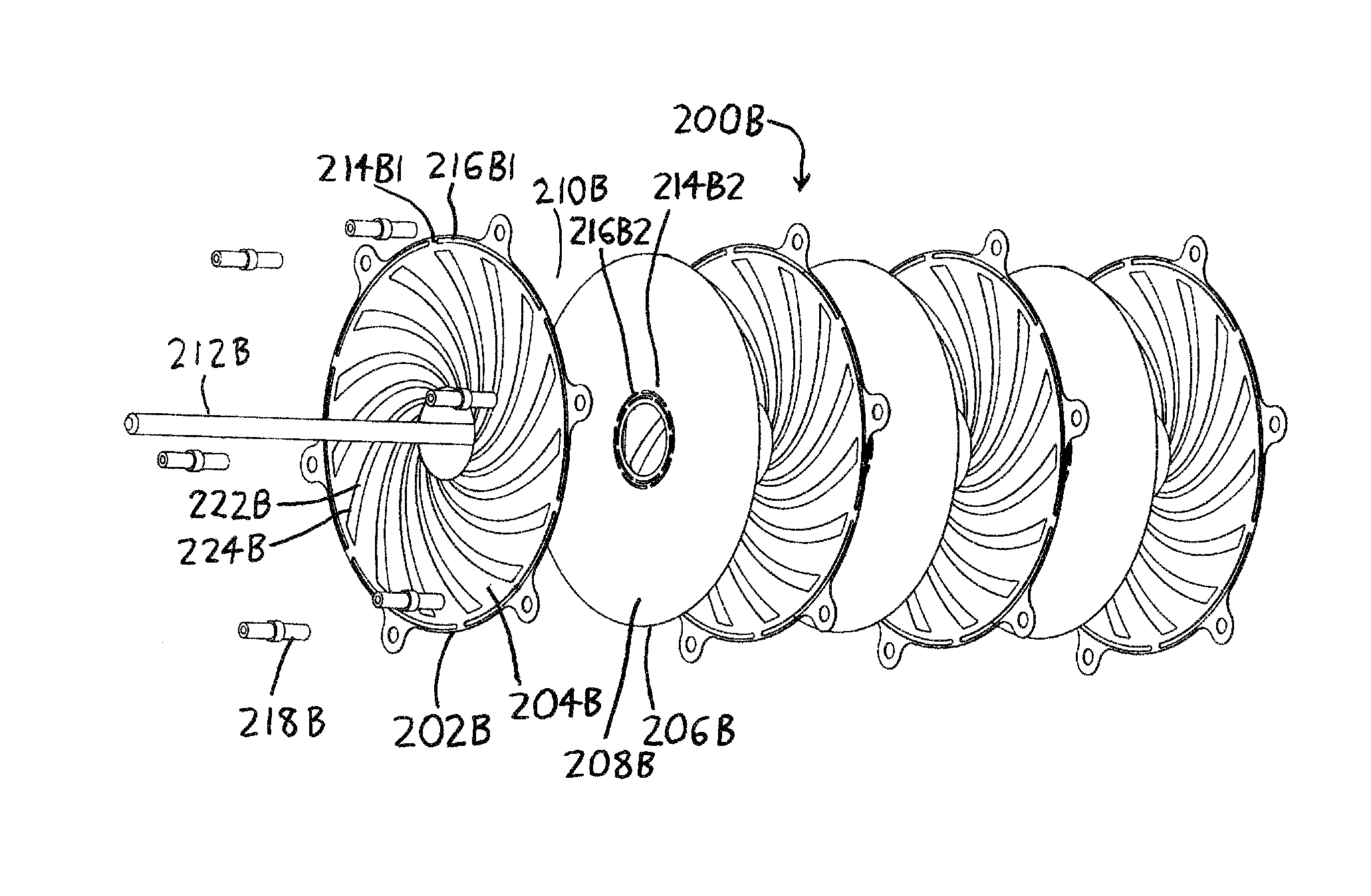
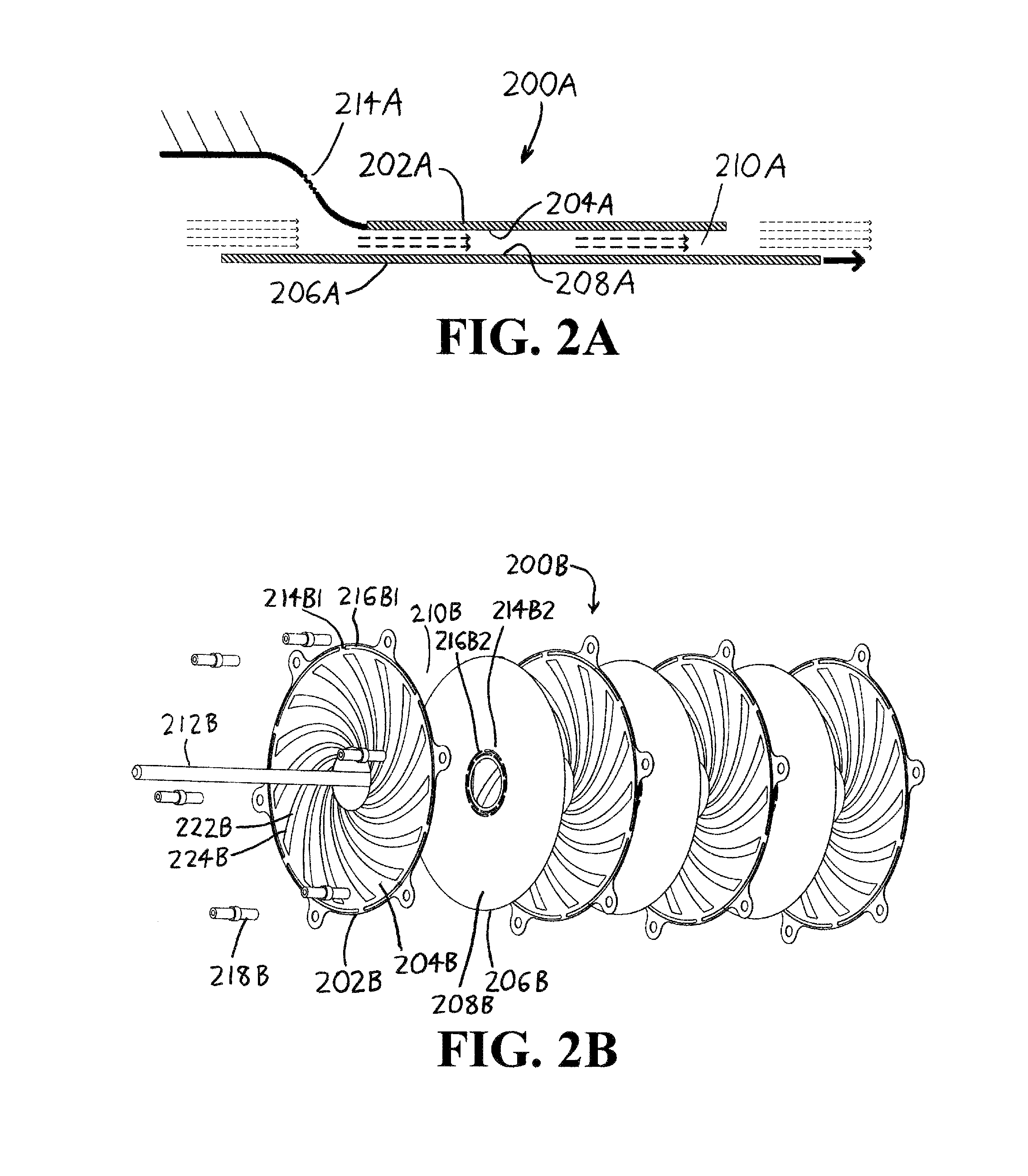
[0032]Expanding on the discussion begin in the “Summary of the Invention” above, preferred versions of the capacitive machines utilize two features. Initially, the machines exploit the fluid boundary layer effects that occur at the interface between a moving surface and a fluid: while in motion, the surface “drags” fluid along with it. If moving and stationary parallel plates are sufficiently close, the moving plate will effectively “pump” fluid between them, with the pressure of the fluid (which is dependent on the speed of plate motion) then helping to maintain separation between the plates. Discontinuities in the plates in the form of flexures and / or flow-modifying walls may then be provided to further assist in maintaining the walls in spaced parallel relationship (where it should be understood that the term “parallel” encompasses both literally parallel and at least substantially parallel alignments). Flexures can be situated on a capacitive machine's plates such that the plate...


PUM


Abstract

Capacitive machines generate torque, generate electric power, and/or transmit electrical signals using closely spaced parallel plates wherein one plate is in motion relative to the other. Closer plate spacing, and thus greater power capacity, is obtained by defining flexures at or near the locations where the plates are anchored to their actuators or mountings, and by defining walls which obstruct fluid flow between one or more of the plates. As one plate is set in motion parallel to the other, thereby inducing fluid flow between the plates, the flow generates a fluid pressure distribution which tends to maintain the plates in spaced relation. In response to the pressure, the flexures allow the plates—which may be out of parallel—to displace and/or tilt from their nominal positions into close parallel relation, thereby providing better capacitance (and thus better torque/power/signal transmission).

Description

CROSS-REFERENCE TO RELATED APPLICATIONS[0001]This application claims priority under 35 USC §119(e) to U.S. Provisional Patent Application 61 / 701,607 filed 15 Sep. 2012, the entirety of which is incorporated by reference herein.FIELD OF THE INVENTION[0002]This document concerns an invention relating generally to capacitive machines, e.g., electrostatic motors, and more specifically to capacitive machines having parallel plates which self-conform during machine operation to maintain a parallel spaced relationship between plates.BACKGROUND OF THE INVENTION[0003]Common electric motors and / or generators operate on electromagnetic principles, and use magnetic fields from permanent magnets and / or wound-wire electromagnets to generate current or mechanical motion. A simple example of this principle is shown in FIG. 1A, where a coil 100A carrying current I winds about a U-shaped “core”102A made of iron (or another ferromagnetic material, i.e., one which is magnetizable), and which has an iro...

Claims


Application Information

Patent Timeline
IPC IPC(8): H02N1/00H02N1/08
CPCH02N1/006H02N1/08H02N1/004
Inventor LUDOIS, DANIEL COLINERICKSON, MICAH JON
Owner C MOTIVE TECHNOLOGIES INC
Why Eureka
Try Eureka