Multiband frequency antenna

a multi-band frequency, antenna technology, applied in the direction of antenna details, non-resonant long antennas, antennas, etc., can solve the problems of reducing the size of the antenna, unable to address the use of parasitic helix antennas, and unable to meet the needs of satellite, handheld devices, and automotive industries, etc., to achieve the effect of reducing size, weight and cost, and a larger area

Active Publication Date: 2016-11-01
TAOGLAS GROUP HLDG LTD
View PDF11 Cites 5 Cited by
  • Summary
  • Abstract
  • Description
  • Claims
  • Application Information

AI Technical Summary

Benefits of technology

[0009]An antenna capable of operating at more than one frequency band, having a single feeding point is disclosed herein. One or more aspects of exemplary embodiments provide advantages while avoiding disadvantages of the prior art. The antenna comprises a first main helix antenna element and a second parasitic helix antenna elements electromagnetically coupled to integrate a single radiofrequency connection structure operating in dual frequency bands. The antenna is designed to be compact and reduce size, weight, and cost, while increasing versatility as compared to equivalent single-band frequency antennas designed using traditional design techniques.
[0011]The specific frequencies of operation and their associated frequency bandwidths of the multiband frequency antenna are determined by the diameter, pitch size or spacing between two adjacent helical elements, and number of turns of the helix antennas. Furthermore, the proximity between the two antenna elements and the amount of overlapping between them should also be considered. In addition, the dielectric permittivity of the medium in which each helix antenna element is wound and the diameter of the wire used to build the helix antenna elements will influence the performance of the overall antenna system.
[0012]By integrating two helical antennas in a coaxial configuration, such that one parasitic helix antenna electromagnetically couples to a main helix antenna connected to a receiver device or a transmitter device, it may be possible to operate these devices at more than one frequency by means of a single RF connection or a single feed. Thus, based on this concept, on top of reducing size, weight, and cost, multiple applications having different frequency bands of operation may be implemented using a single-feed, multiband frequency antenna structure to prevent the need of using multiple antennas, multiple transmission lines, multiple transmitter or receiver ports, and the substantial larger area required to install them.

Problems solved by technology

However, Kraus does not address the use of parasitic helix antennas as a means to provide a multiband frequency antenna using a single feeding point.
Despite these advantages, in the Very High Frequency (VHF) band, the size of the antennas may still be relatively large and impractical for certain applications in the satellite, handheld device, and automotive industries.
However, these efforts have faced certain challenges and limitations.
Specifically, attempts made to provide a multiband helical antenna using concentric or coaxial structures have been limited to multiple feeds or complex and costly configurations.
A major challenge is that multiband antennas requiring multiple feeds are bulkier and heavier, because of the need to use multiple RF connectors, RF cables, and RF ports to connect the multiband antenna system to the corresponding devices, according to the intended applications.
In addition, these antenna systems may be more complex and costly to implement.
Currently, there is no well-established, easy to manufacture multiband antenna design that provides enough bandwidth and operates using a single RF connection or feeding point, especially for applications in the VHF frequency band.

Method used


Image

  • Multiband frequency antenna
  • Multiband frequency antenna
  • Multiband frequency antenna

Examples


Embodiment Construction

[0020]The following description is of one or more aspects of the invention, set out to enable one to practice an implementation of the invention, and is not intended to any specific embodiment, but to serve as a particular example thereof. Those skilled in the art should appreciate that they may readily use the conception and specific embodiments disclosed as a basis for modifying or designing other methods and systems for carrying out the same purposes of the present invention. Those skilled in the art should also realize that such equivalent assemblies do not depart from the spirit and scope of the invention in its broadest form.

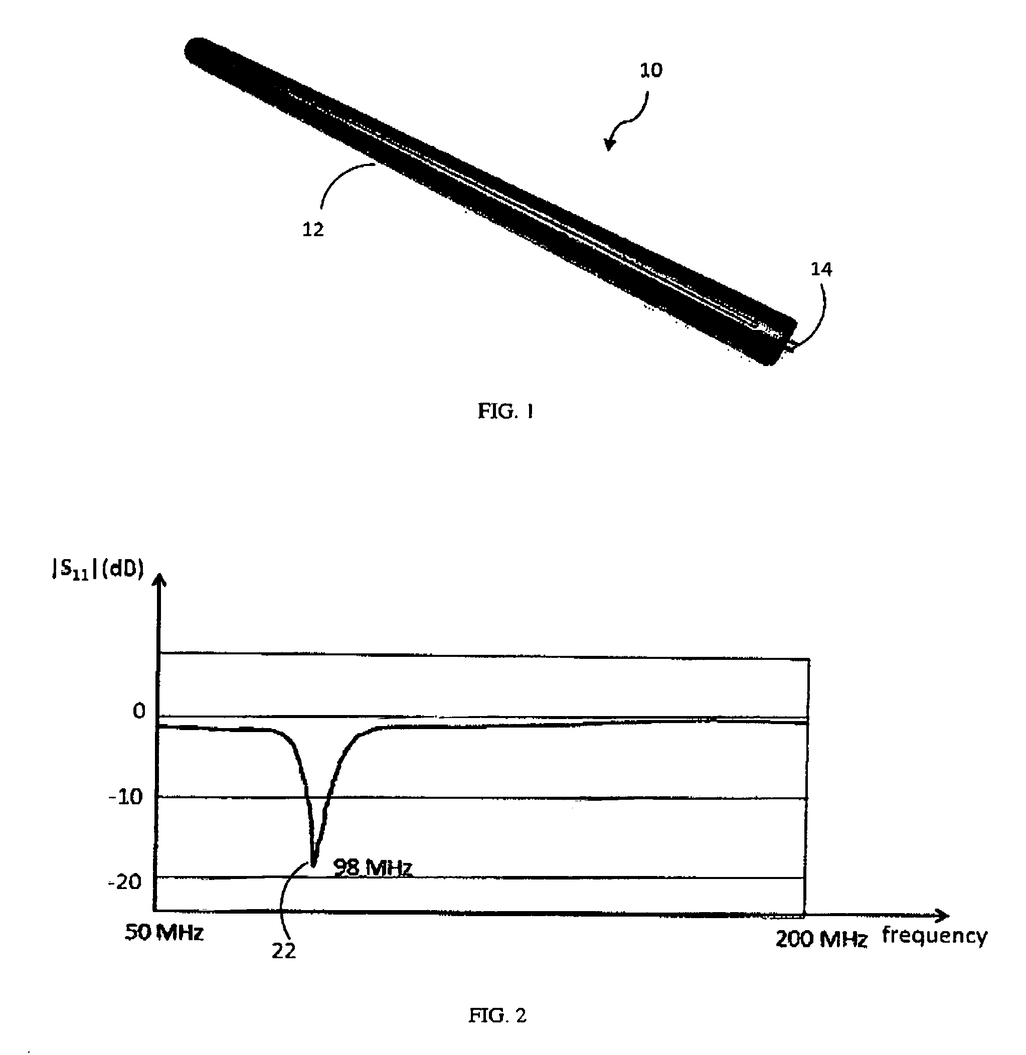
[0021]FIG. 1 shows a commercial 8-in mast antenna 10 used for Frequency Modulation (FM) radio applications. Antenna 10 comprises an antenna radiation element (not shown) contained within antenna enclosure 12. Enclosure 12 provides sturdiness to antenna 10 and protects said antenna radiation element from exposure to environmental effects such as those cause...


PUM


Abstract

Disclosed is an antenna capable of operating at more than one frequency band. The antenna comprises a first main helix antenna element and a second parasitic helix antenna element electromagnetically coupled to integrate a single radiofrequency connection structure operating in dual frequency bands. Furthermore, the antenna is configured to structurally combine a plurality of helix antenna elements to operate at multiple frequency bands having only one radiofrequency connector.

Description

CROSS REFERENCE TO RELATED APPLICATION[0001]This application is based upon and claims priority from co-pending U.S. Provisional Patent Application Ser. No. 61 / 821,576 entitled “MULTIBAND FREQUENCY ANTENNA” filed with the U.S. Patent and Trademark Office on May 9, 2013, by the inventor herein, the specification of which is incorporated herein by reference.FIELD OF THE INVENTION[0002]The present invention relates to antenna systems. More particularly, the present invention relates to an antenna capable of operating at more than one frequency band for use in communication and navigation systems.BACKGROUND OF THE INVENTION[0003]Helical antennas have been used over the last years in multiple radiofrequency (RF) applications. A number of references describe and analyze helical antennas both in single and array configurations. A detailed description of helical antennas is presented in the book titled Antennas, Second Edition, by J. D. Kraus, McGraw-Hill, New York, N.Y., 1988, in Chapter 7....

Claims


Application Information

Patent Timeline
Patent Type & Authority Patents(United States)
IPC IPC(8): H01Q5/00H01Q1/36H01Q5/378H01Q11/08
CPCH01Q1/362H01Q5/378H01Q11/08
Inventor PETROS, ARGY
Owner TAOGLAS GROUP HLDG LTD
Why Eureka
Try Eureka