
Mechanically extendable railroad crossing gate

a technology of railroad crossing gate and mechanical extension, which is applied in the direction of traffic gates, wing accessories, ways, etc., can solve the problems of increasing the likelihood of wind damage to the crossing gate, requiring twice the hardware and maintenance, and affecting the safety of vehicles, etc., to achieve the effect of easy retraction and increased reliability

Active Publication Date: 2016-11-08
SIEMENS MOBILITY INC
View PDF10 Cites 13 Cited by
  • Summary
  • Abstract
  • Description
  • Claims
  • Application Information

AI Technical Summary

Benefits of technology

The present invention provides a mechanical mechanism for controlling the tension of a gate arm in a railroad crossing using a lever, spring, and cable mechanism. This mechanism eliminates the need for solar panels, battery backup, or electro-mechanical devices to drive the gate arm in and out, thereby increasing reliability. Additionally, if an automobile or pedestrian were "trapped" in the crossing, the spring loaded arm could be easily retracted by hand via a handle attached to a retractable arm of the gate arm, thus allowing the automobile or pedestrian to pass through the crossing.

Problems solved by technology

Due to the long length of the gate arm the railroad crossing gate is more likely to suffer wind damage and interfere with overhead obstructions such as power lines.
If the gate arm is damaged in a wind event or is damaged due to overhead obstacles, maintenance crews have to be dispatched to fix the damaged arms or temporarily post warning flags to warn motorists.
There is also the issue of vehicles being “trapped” in the railway crossings by the gate arms.
Some railroad grade level crossings employ “quad gates” that block both lanes of traffic on both sides of the grade crossing, but this requires twice the hardware and maintenance than a standard grade crossing due to double the arms.

Method used


Image

  • Mechanically extendable railroad crossing gate
  • Mechanically extendable railroad crossing gate
  • Mechanically extendable railroad crossing gate

Examples


Embodiment Construction

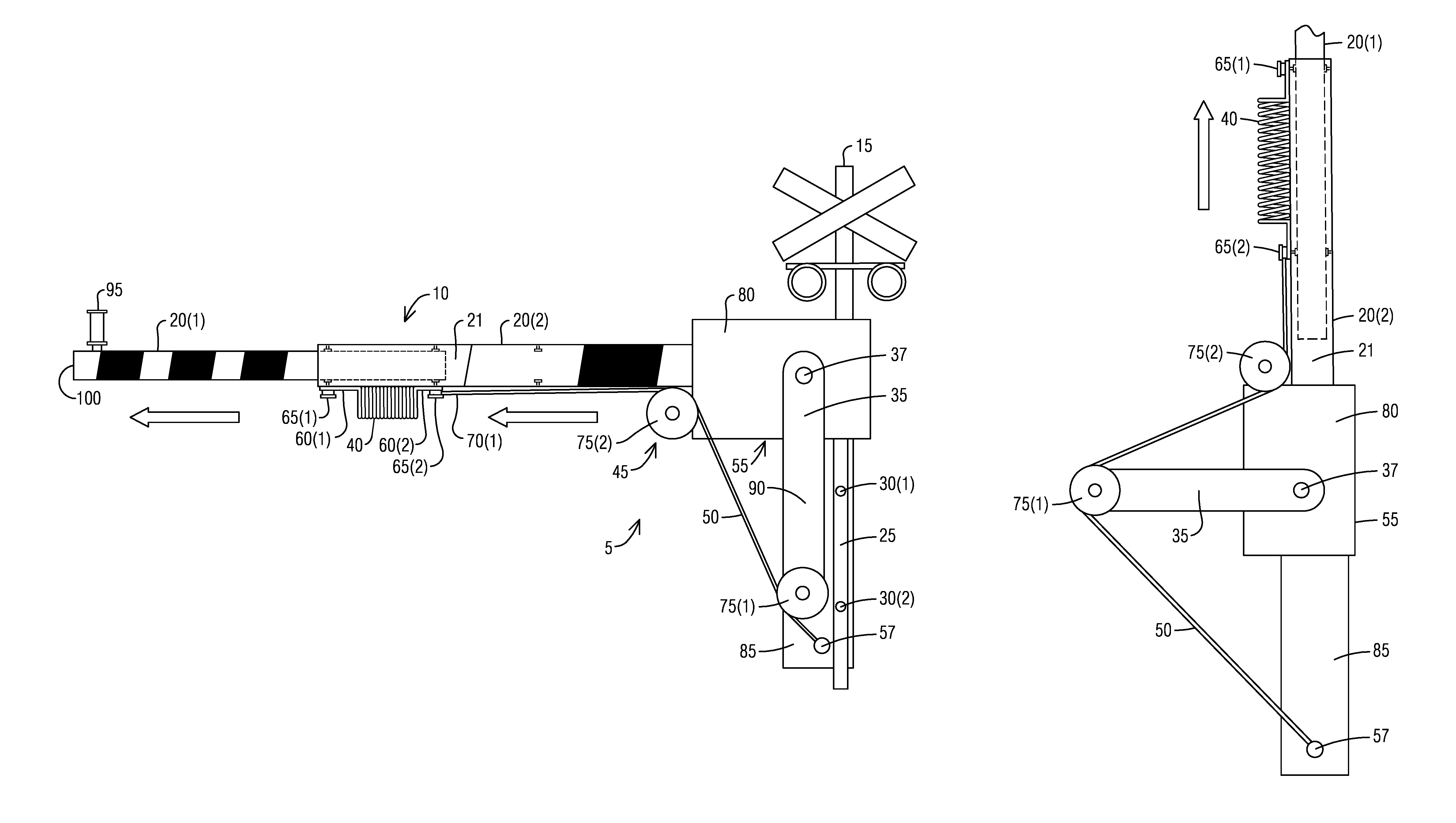
[0018]To facilitate an understanding of embodiments, principles, and features of the present invention, they are explained hereinafter with reference to implementation in illustrative embodiments. In particular, they are described in the context of being a gate with an arm such that it closes the railway crossing yet the gate arm remains relatively short when in the “up” position. The gate arm also mechanically operates. Embodiments of the present invention, however, are not limited to use in the described devices or methods.

[0019]The components and materials described hereinafter as making up the various embodiments are intended to be illustrative and not restrictive. Many suitable components and materials that would perform the same or a similar function as the materials described herein are intended to be embraced within the scope of embodiments of the present invention.

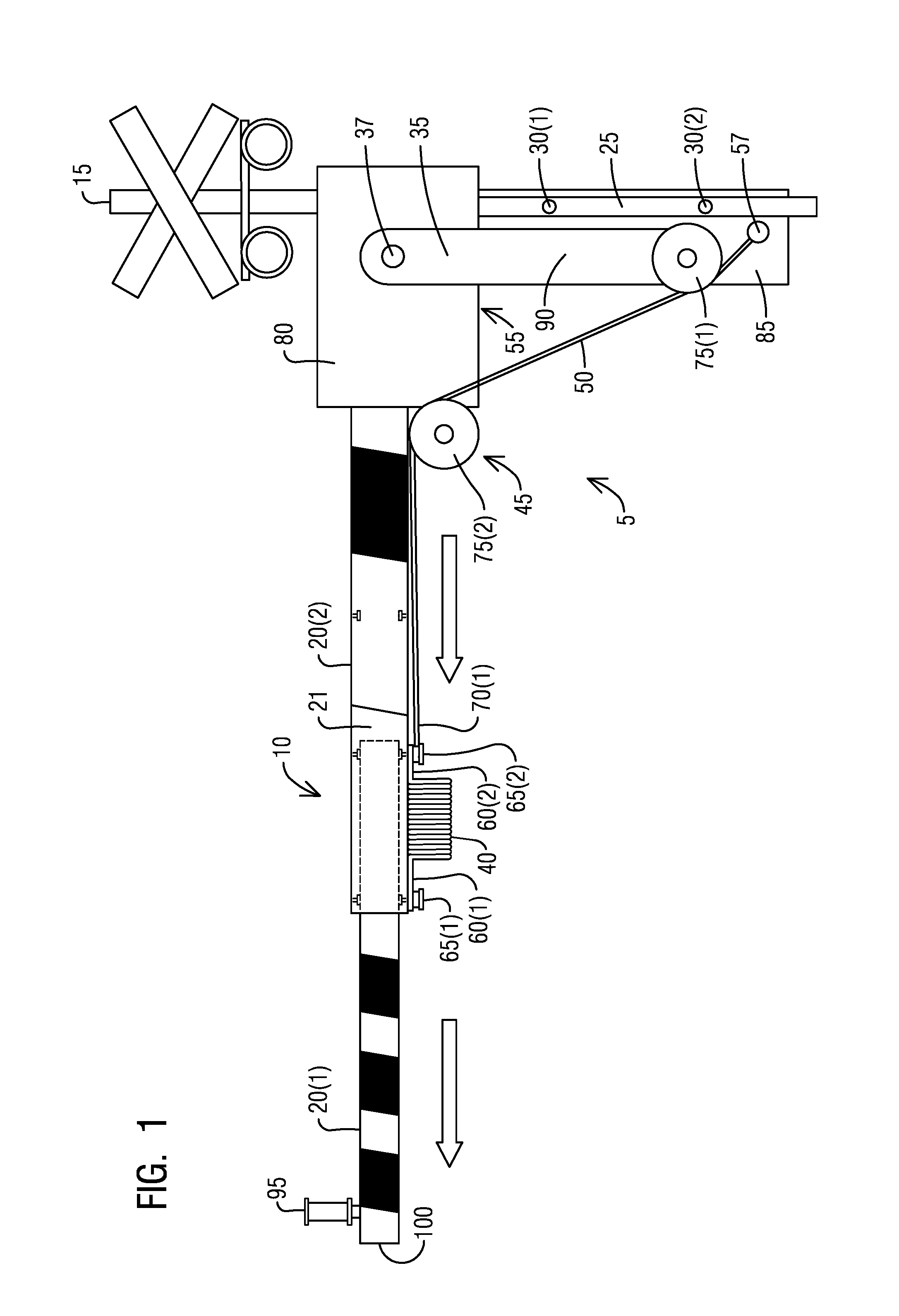
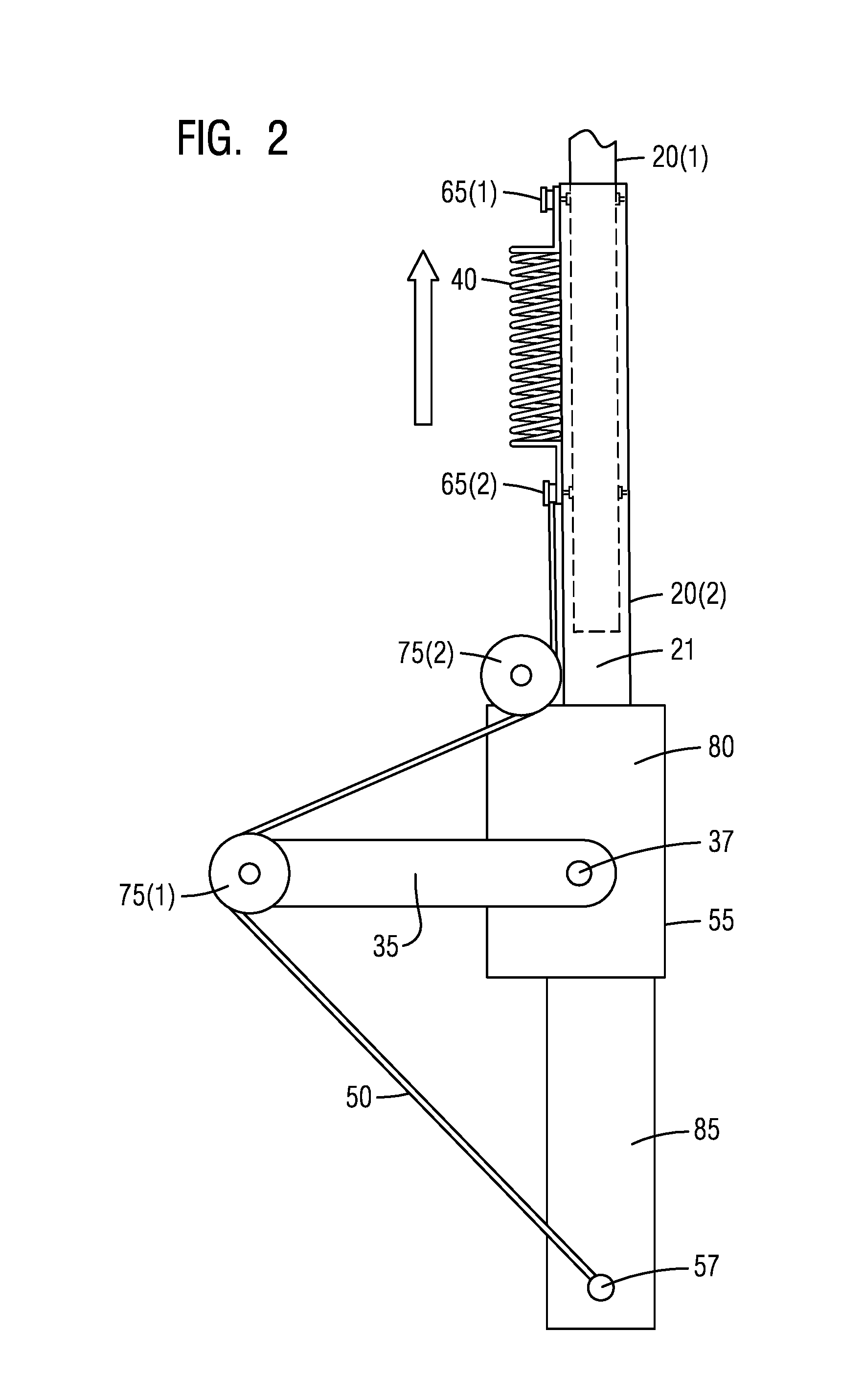
[0020]FIG. 1 illustrates a schematic diagram of a system 5 for operating a gate arm such as a telescopic gate a...


PUM


Abstract

A system for operating a gate arm of a railroad crossing gate is provided. The system includes a lever, a spring attached to an extendable gate arm, a cable mechanism including a cable and a crossing mechanism. The lever is movably coupled to the cable and the spring is coupled to the cable. The lever is coupled to the crossing mechanism and the cable is coupled to the crossing mechanism. The cable mechanism is configured to extend and retract the extendable gate arm and the lever is configured to enable the spring to pull the extendable arm out from a retracted position.

Description

BACKGROUND[0001]1. Field[0002]Aspects of the present invention generally relate to crossing gates and more specifically relates to a railroad crossing gate for use at an intersection of a roadway and a railway track.[0003]2. Description of the Related Art[0004]Railroad grade level crossing gates generally have a relatively long fixed gate arm. Due to the long length of the gate arm the railroad crossing gate is more likely to suffer wind damage and interfere with overhead obstructions such as power lines. If the gate arm is damaged in a wind event or is damaged due to overhead obstacles, maintenance crews have to be dispatched to fix the damaged arms or temporarily post warning flags to warn motorists. There is also the issue of vehicles being “trapped” in the railway crossings by the gate arms.[0005]Railroad grade crossing assemblies with fixed arms use crossing warning signs with or without flashing warning lights. Some railroad grade level crossings employ “quad gates” that block...

Claims


Application Information

Patent Timeline
Patent Type & Authority Patents(United States)
IPC IPC(8): B61L29/04E05F15/646E05F15/643E01F13/06E06B3/92
CPCB61L29/04E01F13/06E06B3/921E05F15/643E05F15/646E05Y2800/122E05F15/611
Inventor PLESS, TRAVISDEJARNATT, BARTON
Owner SIEMENS MOBILITY INC
Learn More