Casing tensioner platform frame and casing tensioner platform frame kit

a technology of casing tensioner and platform frame, which is applied in the direction of machine supports, mechanical equipment, rod connections, etc., can solve the problems of high other problems, and inability to remove the components of the platform frame, so as to ensure the quality and safety of the product, reduce the cost of transportation and installation, and facilitate assembly or disassembly.

Active Publication Date: 2016-11-15
SHANGHAI ZHENHUA HEAVY IND
View PDF37 Cites 5 Cited by
  • Summary
  • Abstract
  • Description
  • Claims
  • Application Information

AI Technical Summary

Benefits of technology

[0025]The casing tensioner platform frame kit and the casing tensioner platform frame assembled by the kit provided by the present invention may be easily assembled or disassembled. The assembly or disassembly is implemented via prefabricated mounting components without any welding. The casing tensioner platform frame kit may be transported in the manner of components and be assembled at field. The cost of transportation and installation is significantly reduced while the quality and safety of the product is ensured.

Problems solved by technology

Most of the existing casing tensioner platform frames have a fixed structure and their components are not removable.
Because of the huge volume and weight of the combined monolithic casing tensioner platform frame, the cost of transportation and installation is very high.
If another method is used, that is, the components are transported separately and are welded at field, other problems will occur.
The drilling platform is positioned on the sea, in an environment of wide temperature variation and high humidity, which is disadvantage to welding and will significantly affect the welding quality.
Thus, welding field on the sea may bring potential safety risks.

Method used


Image

  • Casing tensioner platform frame and casing tensioner platform frame kit
  • Casing tensioner platform frame and casing tensioner platform frame kit
  • Casing tensioner platform frame and casing tensioner platform frame kit

Examples


Embodiment Construction

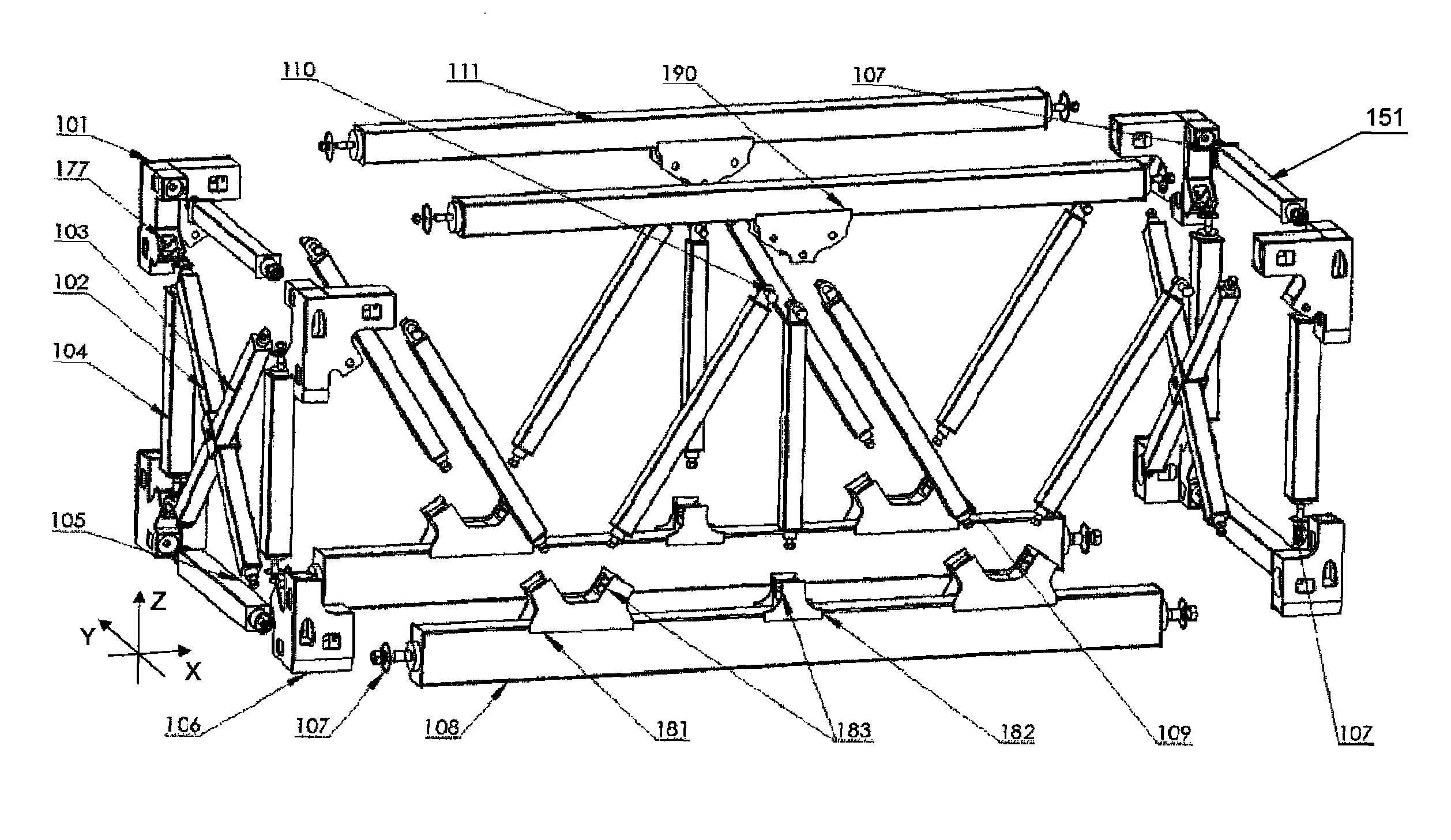
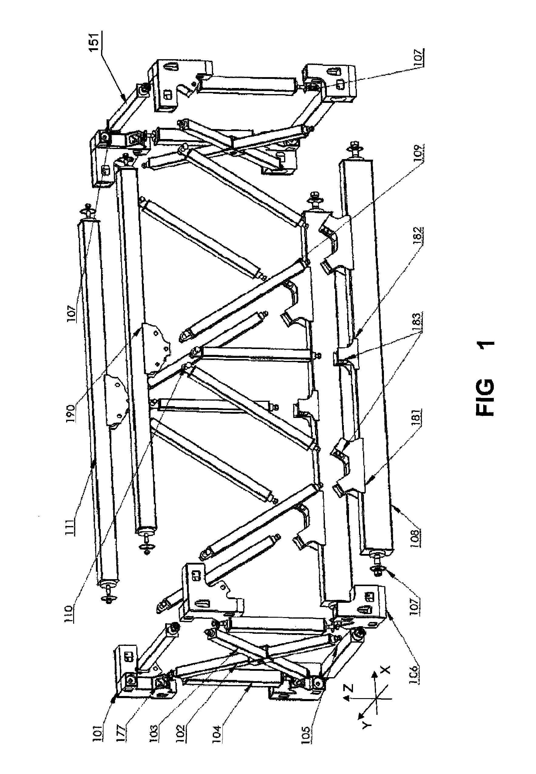
[0032]As shown in FIG. 5, the present invention provides a casing tensioner platform frame. FIG. 5 illustrates an assembled casing tensioner platform frame. FIG. 1 illustrates a kit for assembling the casing tensioner platform frame. Referring to FIG. 1 and FIG. 5, the casing tensioner platform frame comprises:

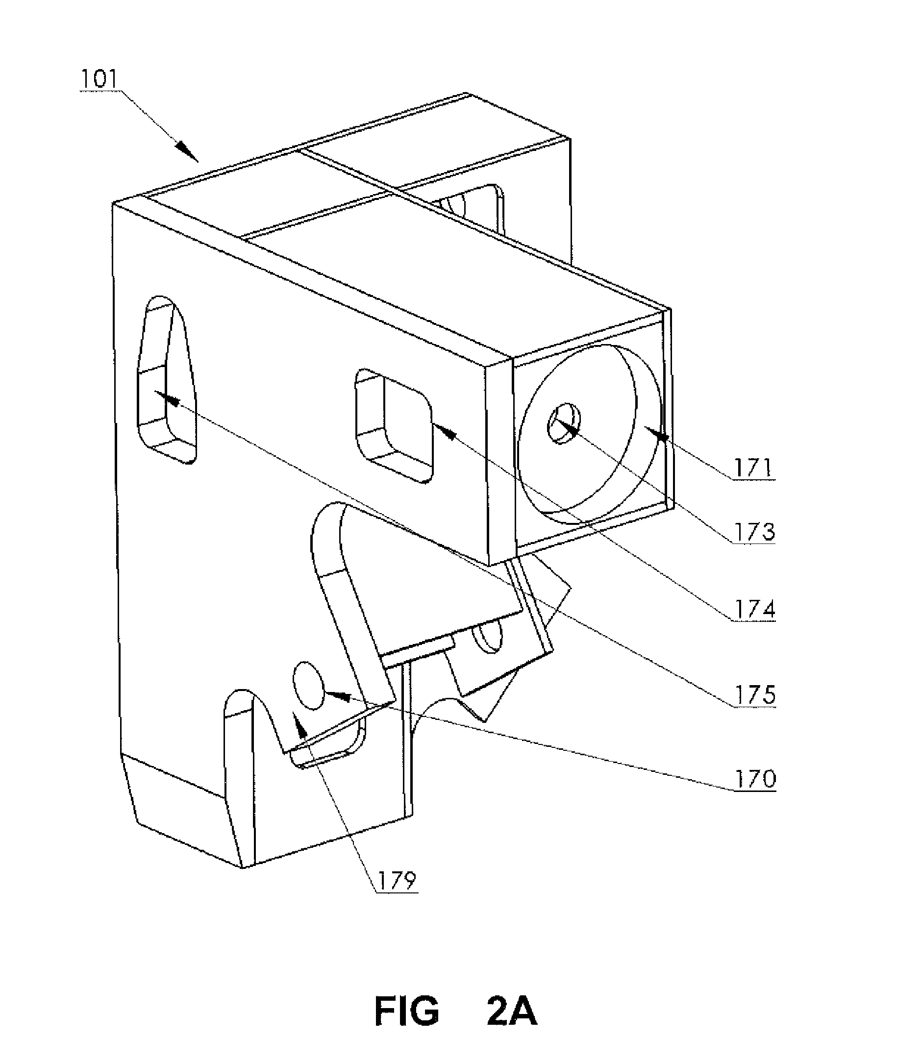
[0033]A frame is composed of four front beams, four lateral beams, four posts and eight corner connectors. The frame is hexahedral and the eight corner connectors are disposed at eight vertexes of the hexahedral frame. According to the embodiment shown in the Figures, the eight corner connectors comprises four top corner connectors 101 disposed at top vertexes and four bottom corner connectors 106 disposed at bottom vertexes. FIGS. 2A and 2B illustrate a top corner connector of the casing tensioner platform frame kit. FIGS. 3A and 3B illustrate a bottom corner connector of the casing tensioner platform frame kit.

[0034]Each of the top corner connector 101 and the bottom corner ...


PUM


Abstract

Embodiments of the present invention disclose a casing tensioner platform frame kit. The kit comprises frame components, corner connectors, rod components and rod connection components. The frame components and the corner connectors form a hexahedral frame. The rod components are fixed on the front planes and lateral planes of the hexahedral frame via the rod connection components. The frame components, corner connectors, rod components and rod connection components are all removable. Embodiments of the present invention also disclose a casing tensioner platform frame. The casing tensioner platform frame kit and the casing tensioner platform frame assembled by the kit provided by the present invention may be easily assembled or disassembled. The assembly or disassembly is implemented via prefabricated mounting components without any welding. The casing tensioner platform frame kit may be transported in the manner of components and be assembled at field. The cost of transportation and installation is significantly reduced while the quality and safety of the product is ensured.

Description

BACKGROUND OF THE INVENTION[0001]1. Field of the Invention[0002]The present invention relates to offshore engineering equipments, more particularly, to offshore drilling equipment.[0003]2. The Related Art[0004]Drilling platform is the most important offshore drilling equipment. A casing tensioner is mounted in a casing tensioner platform frame, which bears the load generated by the casing tensioner during tensioning of the casing. The casing tensioner platform frame is mounted under a cantilever beam and positioned within a moon pool. The casing tensioner is mounted in a casing tensioner platform frame.[0005]Most of the existing casing tensioner platform frames have a fixed structure and their components are not removable. The components are combined in a non-removable manner, such as welding to form a monolithic casing tensioner platform frame on the ground, then the monolithic casing tensioner platform frame are transported and hoisted onto the drilling platform. Because of the hu...

Claims


Application Information

Patent Timeline
Patent Type & Authority Patents(United States)
IPC IPC(8): E04H12/00F16M1/00F16B7/18
CPCF16M1/00F16B7/18E21B19/002F16B7/185E21B19/00E21B19/004E21B19/006
Inventor WANG, KEZHUWU, FUSHENGXU, SULEIFENG, HAO
Owner SHANGHAI ZHENHUA HEAVY IND
Why Eureka
Try Eureka