Apparatus for locating the position of a spinal implant during surgery

a technology for locating the position of a spinal implant and a surgical procedure, which is applied in the field of spinal implants, can solve problems such as difficulty in visualizing under x-rays or fluoroscopy

Active Publication Date: 2016-11-22
SPINEWAVE
View PDF66 Cites 9 Cited by
  • Summary
  • Abstract
  • Description
  • Claims
  • Application Information

AI Technical Summary

Problems solved by technology

One of the issues facing a surgeon during spinal surgery is the proper positioning of the implant in the intradiscal disc space.
However, since such materials are often radiolucent they are difficult to visualize under X-rays or fluoroscopy.

Method used


Image

  • Apparatus for locating the position of a spinal implant during surgery
  • Apparatus for locating the position of a spinal implant during surgery
  • Apparatus for locating the position of a spinal implant during surgery

Examples


Embodiment Construction

[0017]For the purposes of promoting an understanding of the principles of the invention, reference will now be made to the drawing figures and the following written description. It is understood that no limitation to the scope of the invention is thereby intend. It is further understood that the present invention includes any alterations and modifications to the illustrated arrangements and further includes applications of principles of the invention as would normally occur one skilled in the art to which this invention pertains.

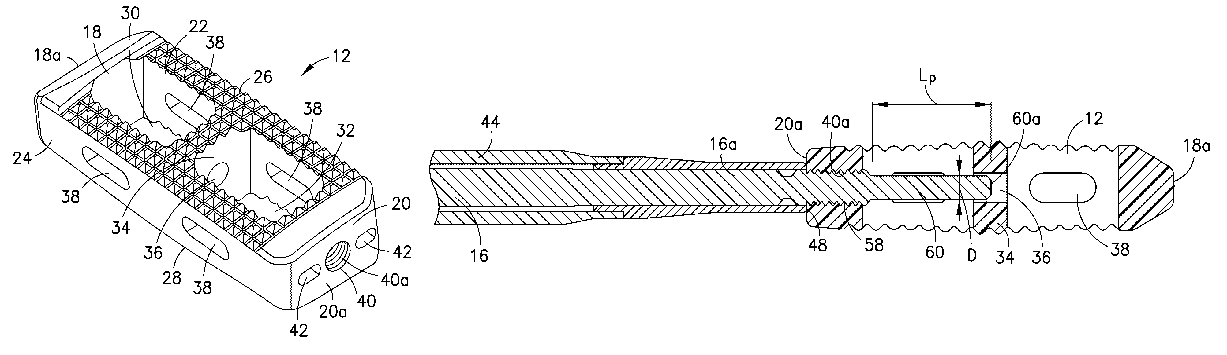
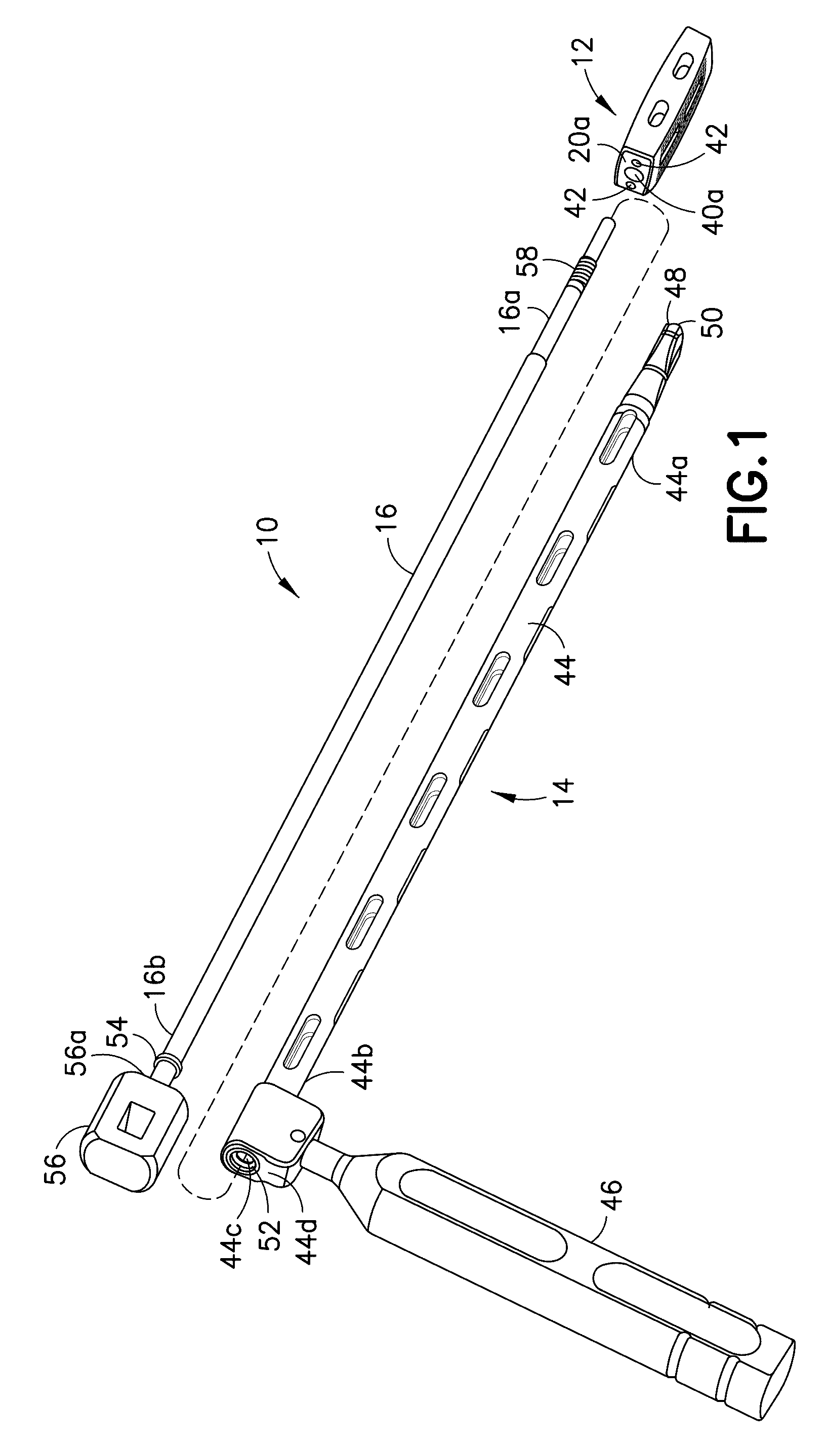
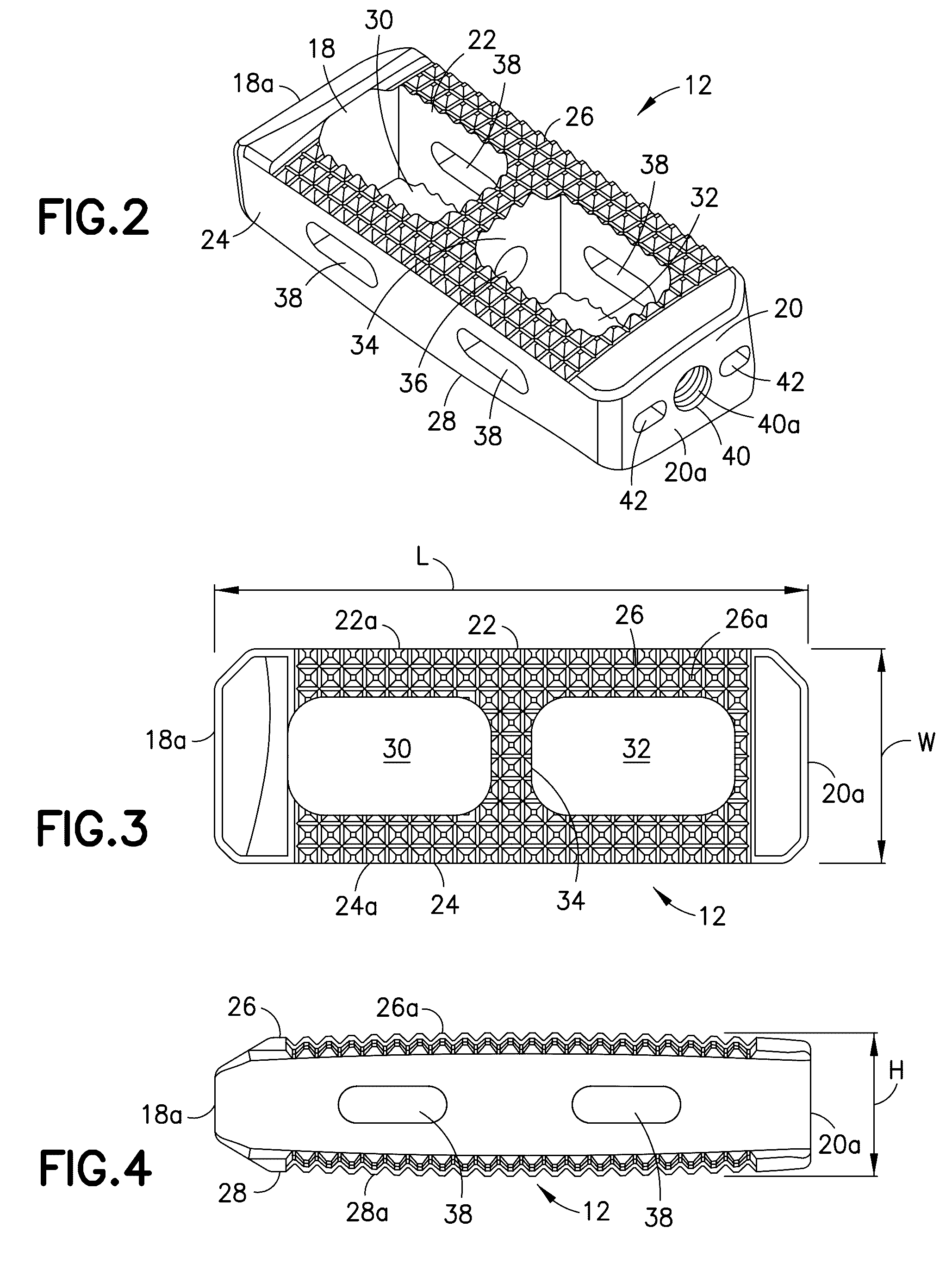
[0018]Referring now to FIGS. 1-4, there is shown an apparatus 10 that includes a spinal implant 12 and an inserter 14 for locating the position of spinal fusion implant 12 in a patient during surgery. In this particular arrangement, spinal implant 12 has a bi-convex configuration for use in interbody spinal fusion and is introduced into the intradiscal space between two opposing vertebral bodies of a patient from the lateral approach. It should be appreciate...


PUM


Abstract

An apparatus and method for locating the position of a spinal implant in an intradiscal space patient during surgery, comprising a spinal implant formed of radiolucent material and a releasably attached inserter comprising a positioning element including thereon a marker of material more radiopaque than the material of the spinal implant. The positioning element extends into the implant such that the marker is positioned at a predetermined location within the implant, the positioning element with the radiopaque maker being removable from the spinal implant after insertion. In a particular method of locating the position of the spinal implant, the spinal implant is inserted from the lateral approach.

Description

FIELD OF THE INVENTION[0001]The subject invention relates generally to the field of spinal implants and more particularly to instruments and methods for locating with imaging techniques the position of such implants during insertion into a patient.BACKGROUND OF THE INVENTION[0002]Implants such as spinal interbody fusion devices are used to treat degenerative disc disease and other damages or defects in the spinal disc between adjacent vertebrae. The disc may be herniated or suffering from a variety of degenerative conditions, such that the anatomical function of the spinal disc is disrupted. Most prevalent surgical treatment for these conditions is to fuse the two vertebrae surrounding the affected disc. In most cases, the entire disc will be removed, except for a portion of the annulus, by way of a discectomy procedure. A spinal fusion device is then introduced into the intradiscal space and suitable bone or bone substitute material is placed substantially in and / or adjacent the de...

Claims


Application Information

Patent Timeline
Patent Type & Authority Patents(United States)
IPC IPC(8): A61F2/46A61F2/44A61F2/30
CPCA61F2/4611A61F2/447A61F2002/3008A61F2002/30774A61F2002/4627A61F2002/4629A61F2002/30593
Inventor VIGLIOTTI, DANIELPENFOLD, ANDREW
Owner SPINEWAVE
Why Eureka
Try Eureka