Method and device for determining a recognition threshold

a recognition threshold and threshold technology, applied in measurement devices, instruments, using electrical means, etc., can solve problems such as linear position errors, signal strength fluctuations, position errors, etc., and achieve the effect of precise determination of tooth position

Active Publication Date: 2016-11-22
ROBERT BOSCH GMBH
View PDF13 Cites 2 Cited by
  • Summary
  • Abstract
  • Description
  • Claims
  • Application Information

AI Technical Summary

Benefits of technology

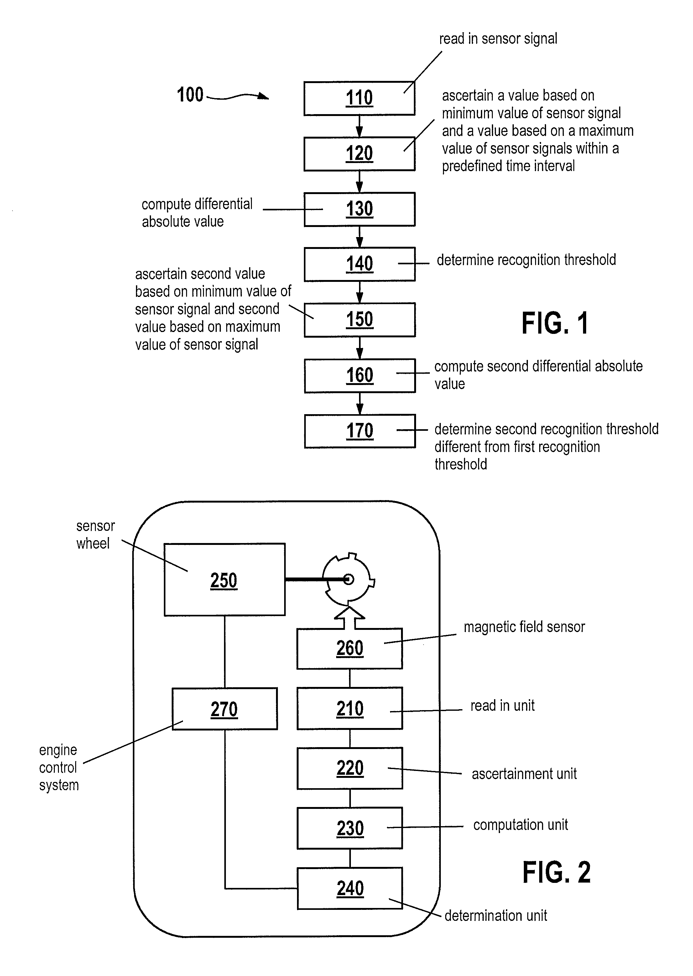
[0019]Thus, the example device is designed to carry out or implement the steps of the example method according to the present invention. In particular, the device may have units which are each designed to carry out one step of the method. In addition, as a result of this design variant of the present invention in the form of a device, the object of the present invention may be achieved quickly and efficiently.
[0026]The present invention may offer the advantage that different sensor signal segments which represent the passing of different teeth and / or gaps in front of the sensor or represent corresponding distances of these teeth or gaps from the sensor result in different recognition thresholds. In subsequent operation of the sensor, this advantageously allows these individual different recognition thresholds to be used for recognizing different teeth, high recognition precision being possible.
[0027]It may also be advantageous if, in the step of computing the second differential absolute value as the second predetermined percentage, a value is used which corresponds to the predetermined percentage that is used in the step of computing the differential absolute value. Such a specific embodiment of the present invention offers the advantage of very simple implementability, since only a single certain percentage needs to be used for determining the particular differential absolute value. At the same time, this certain percentage may also be optimized with respect to values based on experience, at which location the signal curve between the minimum value and the maximum value (or between the averaged minimum value and the averaged maximum value) has the smallest fluctuation range in the predetermined time interval.
[0031]To allow fast learning, i.e., recognition of teeth of the position sensor in real time for a switch-on operation of the sensor, in which a previously determined recognition threshold may not yet be present, the recognition of teeth may be carried out, for example, based on a uniform initial threshold value which is the same for all teeth. For this purpose, the method may have, prior to the ascertainment step, a step of detecting a tooth of the position sensor, the tooth of the position sensor being detected when the sensor signal has a value that is larger than an initial threshold value.

Problems solved by technology

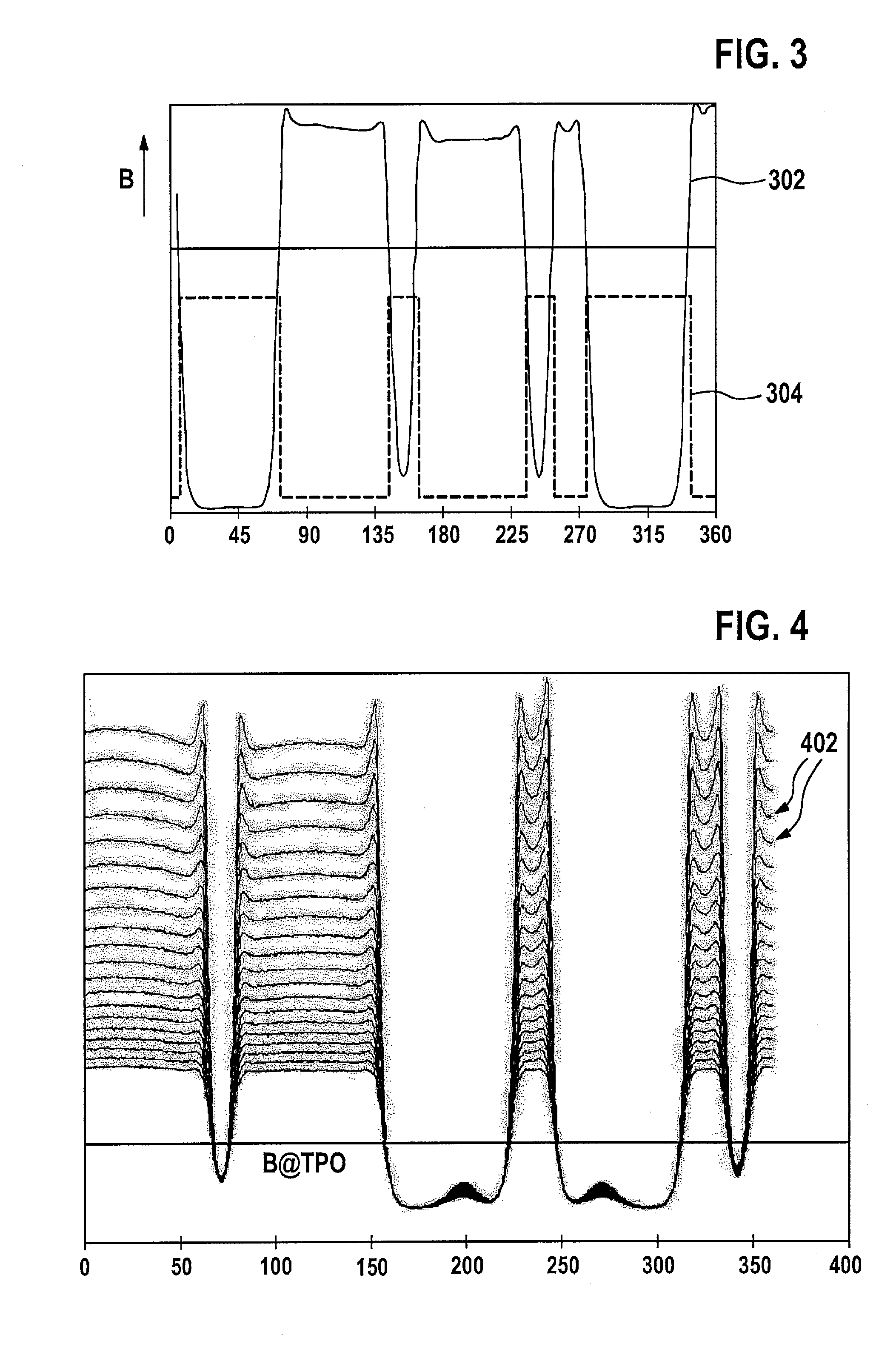
For example, runouts at a position sensor or sensor wheel result in fluctuations in a signal brought about by teeth on the sensor wheel as a position sensor.
Teeth of different height may then result in fluctuations in signal strength.
Since the signal between the teeth and the gaps in-between does not have an infinite slope, this results in a position error during a detection on a fixed level or a fixed signal strength.
In the case of the sensor wheel as a position sensor, the runout results in an angle error in the signal, and in the case of the linear unit as a position sensor, results in a linear position error.

Method used


Image

  • Method and device for determining a recognition threshold
  • Method and device for determining a recognition threshold
  • Method and device for determining a recognition threshold

Examples


Embodiment Construction

[0044]Identical or similar elements may be denoted by identical or similar reference numerals in the figures, and therefore the description is not repeated. In addition, the figures and the description thereof contain numerous features in combination. These features may also be considered individually, or combined to form further combinations not explicitly described herein. Furthermore, the present invention is explained in the description below with the possible use of various measurements and dimensions; the present invention is not to be construed as being limited to these measurements and dimensions. Moreover, method steps according to the present invention may be carried out repeatedly, as well as in a sequence other than that described. An exemplary embodiment which includes an “and / or” conjunction between a first feature / step and a second feature / step may be construed in such a way that according to one specific embodiment, the exemplary embodiment includes the first feature...


PUM


Abstract

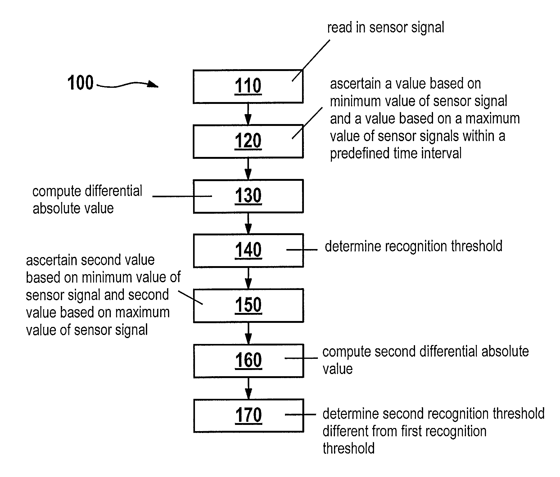
A method for determining a recognition threshold for recognizing the presence of a tooth or a tooth gap of a position sensor in front of a sensor is presented. The method includes a step of reading in a sensor signal which represents a variation over time of a measured magnetic field when the teeth and the tooth gaps of the position sensor are passed by the sensor. In addition, the method includes a step of ascertaining from the sensor signal a first value based on a minimum value of the sensor signal and a first value based on a maximum value of the sensor signal within a predefined time interval. The method also includes a step of computing a differential absolute value which represents a predetermined percentage of a difference between the value based on the at least one maximum value and a value based on the at least one minimum value of the sensor signal. Lastly, the method includes a step of determining the recognition threshold, so that the recognition threshold represents a value that corresponds to a result of adding the differential absolute value to the first value based on the minimum value of the sensor signal.

Description

CROSS-REFERENCE TO RELATED APPLICATIONS[0001]The present application is a national phase of International Patent Application No. PCT / EP2011 / 069148 filed on Oct. 31, 2011, which claims priority under 35 U.S.C. §119 of German Patent Application No. 10 2010 064 203.7 filed on Dec. 27, 2010, the content of all of which are hereby incorporated by reference in their entireties.FIELD[0002]The present invention relates to a method and a computer program for determining a recognition threshold, a device for determining a recognition threshold.BACKGROUND INFORMATION[0003]A conventional phase sensor detects the geometry of a sensor wheel. For this purpose, a signal is evaluated which represents a magnetic variable that is recorded by the sensor when a tooth is passed by the sensor. The sensor recognizes that the tooth has passed by, and “switches,” i.e., recognizes this passing by when a predefined portion of a signal amplitude is exceeded in the magnetic signal detected by the sensor. Since t...

Claims


Application Information

Patent Timeline
Patent Type & Authority Patents(United States)
IPC IPC(8): G01B7/14G01D5/14
CPCG01B7/14G01D5/145
Inventor ROLEW, EDUARDSCHMIDT, VERENAOPITZ, BERNHARD
Owner ROBERT BOSCH GMBH
Why Eureka
Try Eureka