Compact bipositional lateral edge locking load bearing rotation lock mechanism

a technology of load bearing and locking mechanism, which is applied in the direction of instruments, portable computer details, electrical apparatus casings/cabinets/drawers, etc., can solve the problems of limiting affecting the usability, and affecting the usability of the device, so as to improve the usability, enhance the usability, and enhance the effect of ergonomics

Inactive Publication Date: 2016-11-29
INTEGRATED TECH
View PDF56 Cites 18 Cited by
  • Summary
  • Abstract
  • Description
  • Claims
  • Application Information

AI Technical Summary

Benefits of technology

[0011]As stated above and provided in this disclosure, the load bearing rotation lock mechanism disclosed herein may be embodied in various designs that enhance the functionality, ergonomic,

Problems solved by technology

While such devices represent marvels of modern communication, voice recording, photography, videography, gaming and the consumption and documentation of information; they all share a major deficiency that limits their usability; the ability to be positioned to various angles and orientations with respect to a base (a resting surface) in order eliminate glare, steady a camera shot, position the video camera at an optimum angle for recording a scene, for communicating wirelessly with another person over an extended period of time without tiring one's hand, as well as for consuming information while freeing both hands to eat, or to perform other tasks concurrently.
While the ZeroChroma, LLC designs provide mu

Method used


Image

  • Compact bipositional lateral edge locking load bearing rotation lock mechanism
  • Compact bipositional lateral edge locking load bearing rotation lock mechanism
  • Compact bipositional lateral edge locking load bearing rotation lock mechanism

Examples


Embodiment Construction

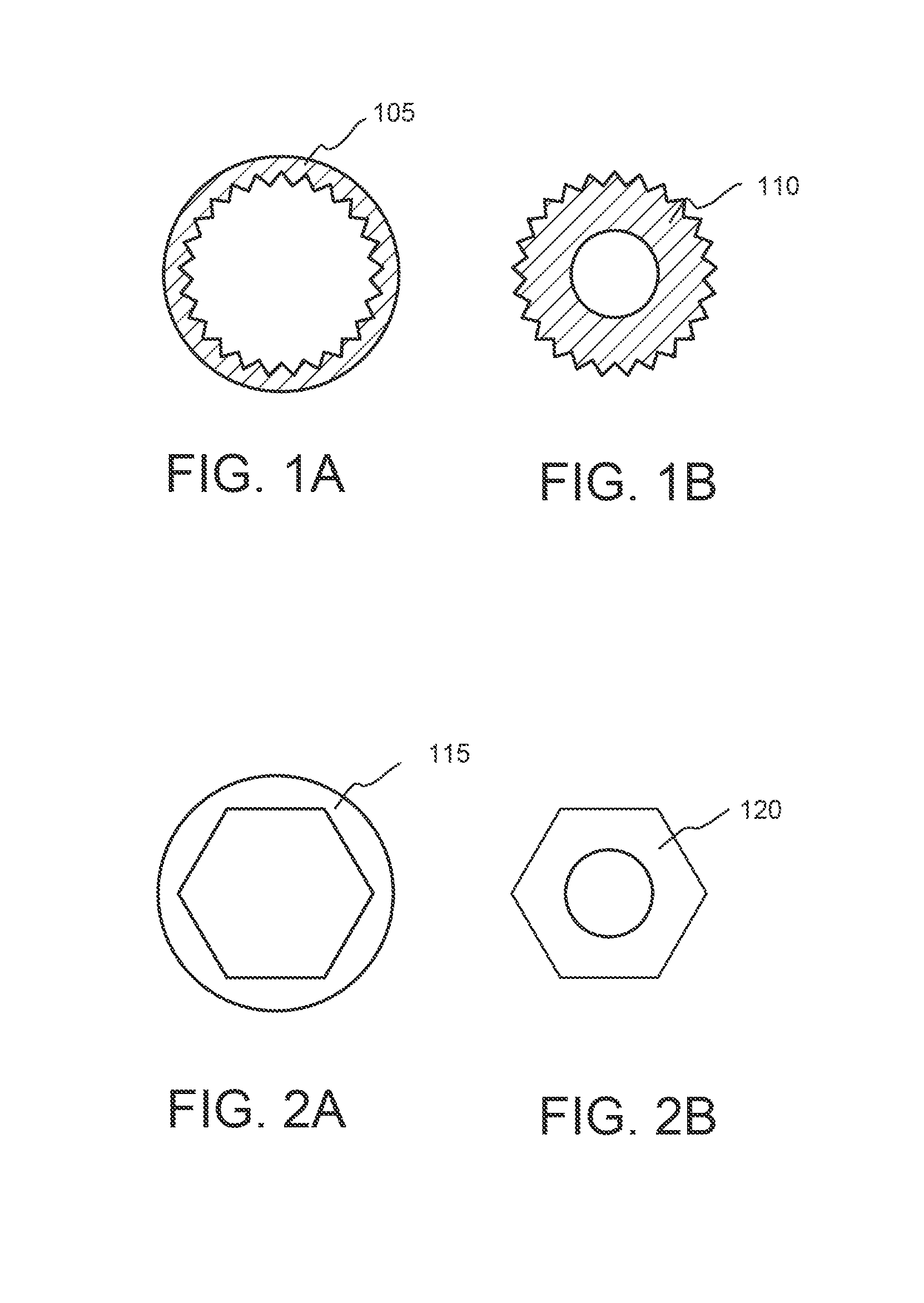
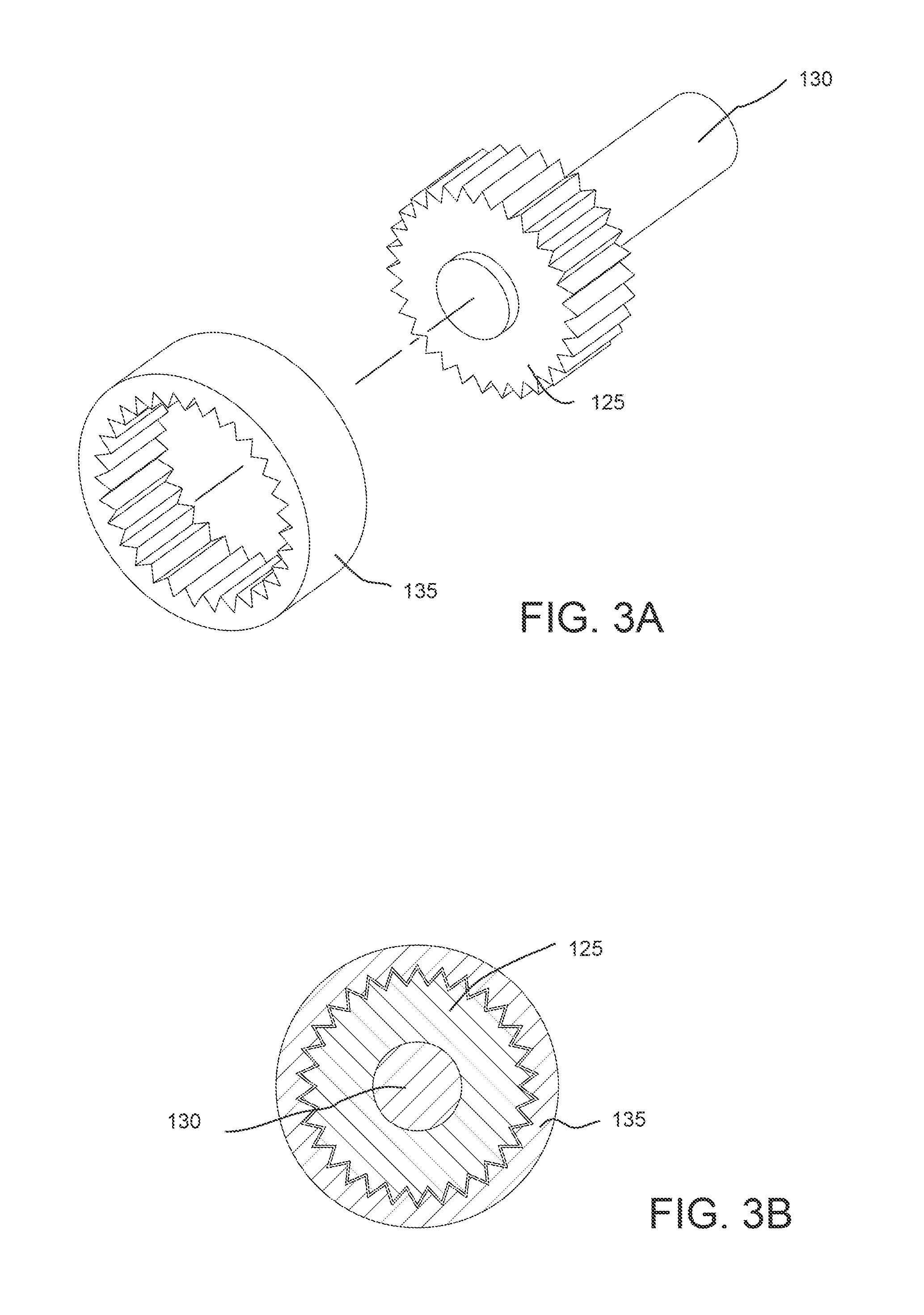
[0091]FIG. 1A represents a cross-sectional embodiment of an internal gear 105, and FIG. 1B represents a cross-sectional embodiment of a spur gear 110. Generally speaking, spur gears or straight-cut gears are a simple type of gear consisting of a cylinder or disk with the teeth projecting radially, where the edge of each tooth is straight and aligned parallel to the axis of rotation. These gears can be meshed together correctly if they are fitted to a common axis, shaft, or channel. These illustrations are used to illuminate the essence of this invention which is that of two disks or cylinders with teeth or a combination of both that can interlock radially between their inner and outer surface areas, or frontal areas, or both, where one of the disks or cylinders is attached to a fixed surface area and the other disk or cylinder is attached to a pivoting arm, plate, or other kind of load bearing support element, and where one of the disks or cylinders is able to mesh (lock) and un-mes...


PUM


Abstract

A load bearing rotation lock mechanism including disks or cylinders with teeth or a combination of both that interlock radially between their inner and outer surface areas, or frontal areas, or both, where one of the disks or cylinders is attached to a fixed surface area and the other disk or cylinder is attached to a pivoting arm, plate, or other kind of load bearing support element, and where one of the disks or cylinders is able to mesh (lock) and un-mesh (unlock) from the other disk or cylinder by protruding, retracting, or sliding laterally over a common, continuous or divided axis, shaft, or channel thereby freezing the angular position of the pivoting arm, plate, or other kind of load bearing support element with respect to the fixed surface area at the time the disks, cylinders, or a combination of both, mesh (lock) with each other and unfreezing the pivoting arm, plate, or other kind of load bearing support element to pivot freely with respect to the fixed surface area when the disks, cylinders, or combination of both un-mesh (unlock) from one another.

Description

CROSS-REFERENCES TO RELATED APPLICATIONS[0001]This application is a continuation-in-part (CIP) of U.S. patent application Ser. No. 14 / 488,054, filed Sep. 16, 2014, and claims the benefit of U.S. patent application Ser. No. 14 / 255,711, filed Apr. 17, 2014, and claims the benefit of U.S. Provisional Application 62 / 064,216 filed Oct. 15, 2014, and U.S. Provisional Application 62 / 060,353 filed Oct. 6, 2014, and U.S. Provisional Application 61 / 906,878 filed Nov. 20, 2013, and U.S. Provisional Application 61 / 878,491 filed Sep. 16, 2013, all of which applications are incorporated by reference in their entireties.FIELD[0002]This technology relates to simple and compact mechanisms for locking and unlocking the rotation of load bearing hinges at multiple specific angles. More particularly, the technology herein relates to the specific angular positioning of personal information display and input devices among other applications.BACKGROUND OF THE INVENTION[0003]Since the introduction of the Ap...

Claims


Application Information

Patent Timeline
IPC IPC(8): E05D11/10E05D3/02H05K5/02
CPCE05D11/1028E05D11/1007E05D3/022H05K5/0234H05K5/0226E05D2011/1035A45C11/00A45C13/36G06F1/1626G06F1/166G06F1/1669G06F1/1679G06F3/0208A45C2011/003A45C2200/15G06F2200/1633G06F2200/1634E05Y2900/606E05D7/1011F16M11/10F16M13/005F16M2200/08G06F1/1681G06F1/16
Inventor ZALOOM, JOSEPH
Owner INTEGRATED TECH
Why Eureka
Try Eureka