Identifying forces in a well bore

a technology of identifying forces and well bores, applied in the field of identifying forces, can solve problems such as well bore collapse, no longer being moved, and stuck casings

Active Publication Date: 2016-12-06
BP EXPLORATION OPERATING CO LTD
View PDF22 Cites 0 Cited by
  • Summary
  • Abstract
  • Description
  • Claims
  • Application Information

AI Technical Summary

Benefits of technology

[0018]Viscous drag forces are caused by the displacement of fluid in the well. The displaced fluid opposes any movement of the member, and thereby varies the force on the moveable unit. Viscous drag forces tend to build up during a given cycle, therefore by looking at the variation of the load values during a given cycle, in particular by looking for a monotonic change in the values, a measure of the viscous drag can be made. From this measure, the likelihood of, for example fracturing in the well bore caused by the fluid movement, can be established and the movement of the member can be adjusted accordingly (i.e. reducing or increasing the speed of movement).
[0020]One cycle may provide an erroneous result, or equally, static friction may be high during one cycle, but as it is overcome, the cause is removed and the static friction does not reoccur. Consequently, to provide accurate results, it is a benefit that multiple cycles can be compared to discover trends in the data. These trends can be used to identify a developing cause of static friction and therefore a high risk of the member becoming stuck.
[0025]It is advantageous to correctly identify the period in which the load values are truly representative of the weight of and friction on the moveable unit. Therefore by identifying the period described above, errors associated with the transfer of load from the moveable unit to the slips and vice versa can be avoided.

Problems solved by technology

A casing string (or other tubular member), being moved within a well bore may become stuck such that it can no longer be moved (either rotated or moved axially, up or down).
Such situations, often known as ‘stuck casing’ or ‘stuck pipe’, are generally caused by excessive static friction along the well bore.
One particular cause of a ‘stuck pipe’ is “differential sticking”, which is a situation where a tubular member is pressed against the side of a well bore so that it contacts the side of the well bore along a substantial length of the tubular member; however other causes of a stuck pipe are well bore collapse or some form of instability in the well bore.
A stuck pipe is one of the greatest problems involved with drilling a well bore, and can result in many days of lost productivity, result in losses to equipment (because the casing string or other tubular member cannot be recovered), and can reduce the output of a resultant well (due to narrower bore tubing having to be run down the stuck tubing).
Therefore, it has been found that the measures of hook load, and therefore measures of dynamic friction as described above, are unable to identify the magnitude or nature of static friction in a well bore.
A further problem which may occur when moving a member in a well bore, either to run-in or pull out the member, is that the movement of the member causes a downhole pressure wave.
This pressure wave may cause damage to the formation, and may cause fluid to leak out of or be drawn into the formation.

Method used


Image

  • Identifying forces in a well bore
  • Identifying forces in a well bore
  • Identifying forces in a well bore

Examples


Embodiment Construction

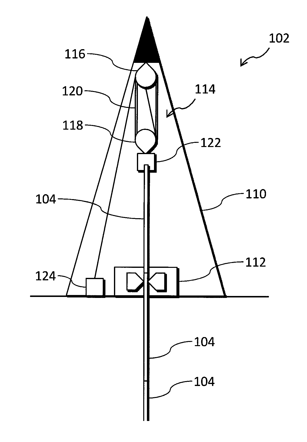
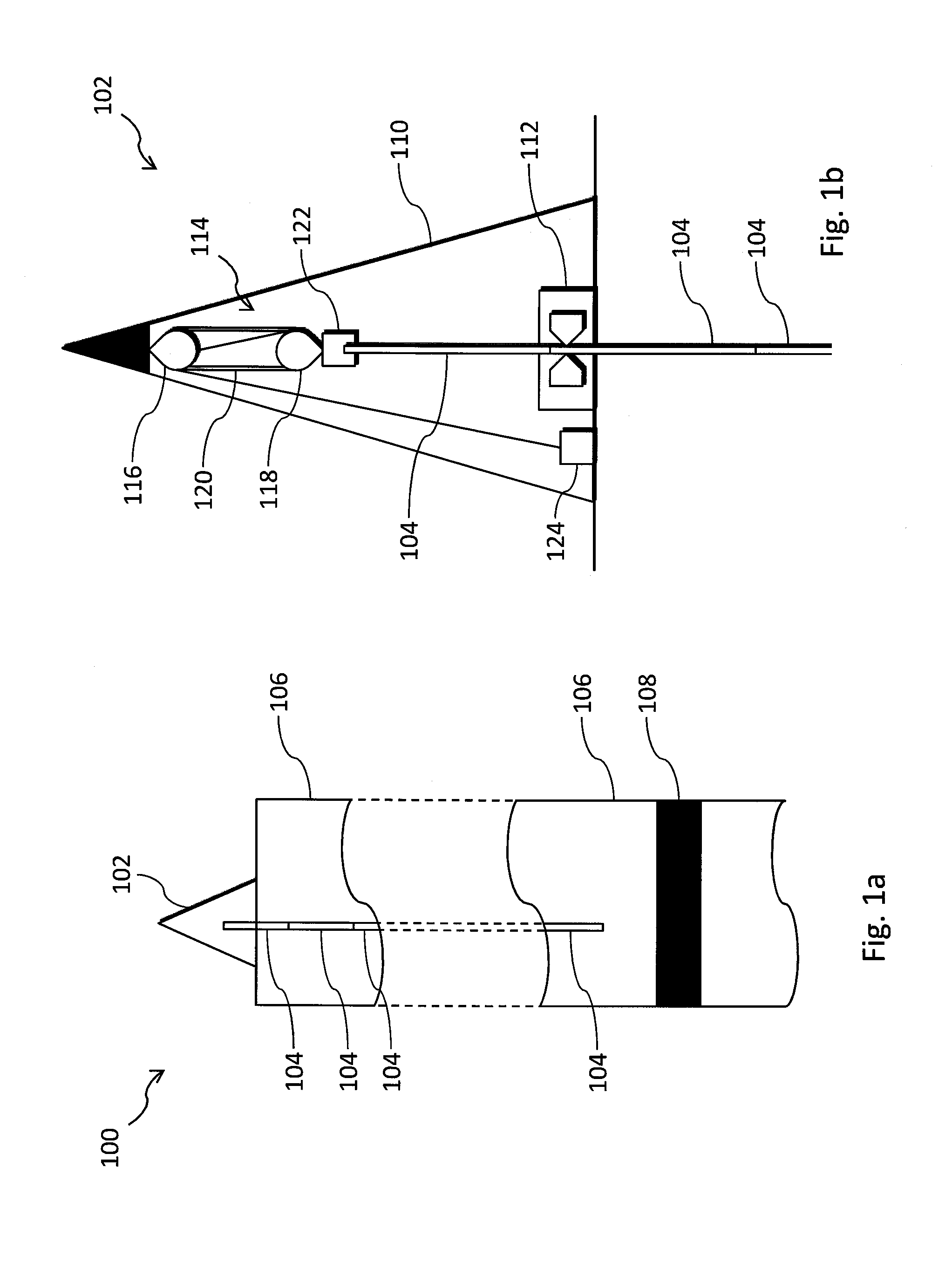
[0047]FIG. 1a shows a schematic diagram of a drilling rig system 100 with which embodiments may be used. The embodiment below will be described generally in the context of a casing string being lowered by a drilling rig into an oil well bore. However it will be apparent that embodiments are not limited to such situations, and includes the situations in which any member, in particular, a tubular member, is moved (i.e. lowered or raised) within a well bore. Such situations would include, but are not limited to, the drilling of both production and injection wells for a oil or gas recovery system, as well as the drilling of well bores into aquifers and the like.

[0048]The system 100 comprises a drilling rig 102 which is configured to drill into the rock formations below it. A casing string, comprising a plurality of joints 104, is shown extending into the rock formations from the rig 102. The rock formations comprise a first layer 106, below which a hydrocarbon bearing reservoir 108 is l...


PUM


Abstract

A member is moved within a well bore in a plurality of cycles, each cycle including holding the member in slips, releasing the slips, moving the member within the well bore and applying the slips. The hook load is measured at multiple points during each of these cycles and the plurality of measured values are used to identify data indicative of the forces on the member within the well bore.

Description

CROSS-REFERENCE TO RELATED APPLICATIONS[0001]This application is a 35 U.S.C. §371 national stage application of PCT / EP2012 / 070750 filed Oct. 19, 2012 and entitled “Identifying Forces in a Well Bore,” which claims priority to PCT / GB2011 / 001505 filed Oct. 19, 2011 and entitled “Identifying Friction in a Well Bore,” both of which are hereby incorporated herein by reference in their entirety for all purposes.FIELD OF THE INVENTION[0002]The present invention relates to systems and methods for identifying forces on a member being moved within a well bore, and in particular for identifying such forces from surface measurements measured by a rig to which the member is attached. The present invention is particularly suited for employment when the member is a tubular member, for example, a casing string, liner string or a tubing string such as a drill string, injection tubing string, or a production tubing string.BACKGROUND[0003]During and after the drilling of a well bore, tubular members ar...

Claims


Application Information

Patent Timeline
Patent Type & Authority Patents(United States)
IPC IPC(8): E21B44/00E21B47/00G01V1/40G01V3/18
CPCE21B47/0006E21B44/00E21B47/00E21B47/007
Inventor MASON, COLIN JAMESSTREETER, EDWARD JAMES
Owner BP EXPLORATION OPERATING CO LTD
Why Eureka
Try Eureka