Turning system

a turning system and turning shaft technology, applied in the direction of electric steering, power steering steering, vehicle components, etc., can solve the problems of large drag force, large change of turning angle, and end of rack shaft may come into contact with the rack housing with a large force, so as to improve the steering feeling of the driver and facilitate the calculation of the target steering torqu

Active Publication Date: 2020-10-29
JTEKT CORP
View PDF2 Cites 2 Cited by
  • Summary
  • Abstract
  • Description
  • Claims
  • Application Information

AI Technical Summary

Benefits of technology

[0018]Since the steering operation amount can be converted to a torque required for the electric motor, a force which is applied from the vehicle side to turn the turning wheels is determined based on the steering operation amount and the steering torque and this force can be converted to a lateral force. On the other hand, a targe...

Problems solved by technology

When a driver cannot be aware thereof, there is concern that a state in which a torque which is input to a steering wheel by the driver is greater may be maintained and thus the end of the rack shaft may come into contact with the rack housing with a large force.
When the drag force resisting an operation of the steering wheel for increasing the magnitude of the turning angle when the ...

Method used


Image

  • Turning system
  • Turning system
  • Turning system

Examples


Embodiment Construction

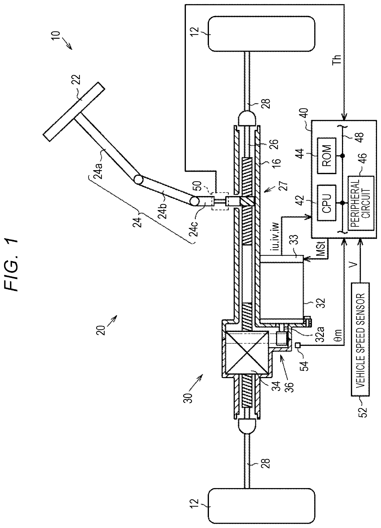
[0028]Hereinafter, a turning control system according to a first embodiment will be described with reference to the accompanying drawings. As illustrated in FIG. 1, an electric power steering system 10 includes a steering mechanism 20 that turns turning wheels 12 based on a driver's operation of a steering wheel 22 and a turning actuator 30 that electrically turns the turning wheels 12.

[0029]The steering mechanism 20 includes a steering wheel 22, a steering shaft 24 that is fixed to the steering wheel 22, and a rack and pinion mechanism 27. The steering shaft 24 includes a column shaft 24a that is connected to the steering wheel 22, an intermediate shaft 24b that is connected to a bottom end of the column shaft 24a, and a pinion shaft 24c that is connected to a bottom end of the intermediate shaft 24b. A bottom end of the pinion shaft 24c is connected to a rack shaft 26 via the rack and pinion mechanism 27. Right and left turning wheels 12 are connected to both ends of the rack shaf...


PUM


Abstract

A turning system includes a steering wheel, a turning actuator that has an electric motor incorporated thereinto and turns turning wheels, and a control device. The control device is configured to perform: a steering operation amount calculating process of calculating a steering operation amount; an angle command value calculating process of calculating an angle command value; an angle operation amount calculating process of calculating an angle operation amount; an operation process of operating a drive circuit of the electric motor; and a correction process of correcting a parameter upstream from the angle operation amount calculating process such that a drag force resisting an operation of the steering wheel for increasing magnitude of the turning angle is applied when the magnitude of the turning angle is equal to or greater than a turning angle threshold value.

Description

CROSS-REFERENCE TO RELATED APPLICATION[0001]This application claims priority to Japanese Patent Application No. 2019-086314 filed on Apr. 26, 2019, incorporated herein by reference in its entirety.BACKGROUND1. Technical Field[0002]The disclosure relates to a turning system that operates a turning actuator having an electric motor incorporated thereinto and turning a turning wheel.2. Description of Related Art[0003]For example, Japanese Patent Application Publication No. 2006-175940 (JP 2006-175940 A) discloses a device that operates an electric motor which is incorporated into a turning actuator which turns turning wheels based on an operation amount in feedback control based on a difference between a target steering torque and an actual steering torque and an operation amount in feedback control based on a difference between a target turning angle and a turning angle.[0004]In an electric power steering system (a steering assist system), it is generally known that turning by a tire ...

Claims


Application Information

Patent Timeline
IPC IPC(8): B62D5/04B62D15/02B62D5/00
CPCB62D5/0463B62D5/006B62D15/021B62D5/0469B62D6/008
Inventor TAMAIZUMI, TERUTAKA
Owner JTEKT CORP
Why Eureka
Try Eureka