Single wire seal for sealing an electric cable in an aperture of a terminal

a technology of single wire seal and terminal, which is applied in the direction of cable inlet sealing means, securing/insulating coupling contact members, and coupling device connections, etc., can solve the problems of substantial deformation of the materials of the relatively soft single wire seal, and achieve the effect of faster and more cost-effectiv

Active Publication Date: 2016-12-06
APTIV TECH LTD
View PDF16 Cites 5 Cited by
  • Summary
  • Abstract
  • Description
  • Claims
  • Application Information

AI Technical Summary

Benefits of technology

[0011]Therefore, the crimping portion of the single wire seal of the present invention is further provided with a reinforcement element. The reinforcement element improves the crimping, “protects” the single wire seal during the crimping and reduces deformations of the relatively soft single wire seal. Therefore, the sealing properties and the minimum pull force remain fairly constant and the risk of a loosening of the crimped connection between the electric cable and the single wire seal is reduced. The reinforcement element is arranged at and preferably around the crimping portion of the single wire seal and is provided with at least one ring shaped portion or preferably with two to four ring shaped portions axially spaced apart from each other. The ring shaped portion can be continuous or intermittent over the ring circumference. The reinforcement element is molded from a second material, and in particular a plastic material, which has a higher Young's modulus E2 than the first material.
[0020]Due to its configuration, the singe wire seal may be manufactured by a two-component molding process which is faster and more cost-effective, than two conventional molding procedures or an assembly from two or more pre-prepared parts.

Problems solved by technology

Due to the relatively soft material of the single wire seal, this crimping leads to a substantial deformation of the materials of the relatively soft single wire seal.

Method used


Image

  • Single wire seal for sealing an electric cable in an aperture of a terminal
  • Single wire seal for sealing an electric cable in an aperture of a terminal
  • Single wire seal for sealing an electric cable in an aperture of a terminal

Examples


Embodiment Construction

[0025]It is an object of the present invention to improve the situation described above in the BACKGROUND OF THE INVENTION by providing an improved single wire seal which can be crimped without degrading the sealing properties and the minimum pull force requirements. It is another object of the present invention to provide single wire seals which can be manufactured with reduced number of steps and costs.

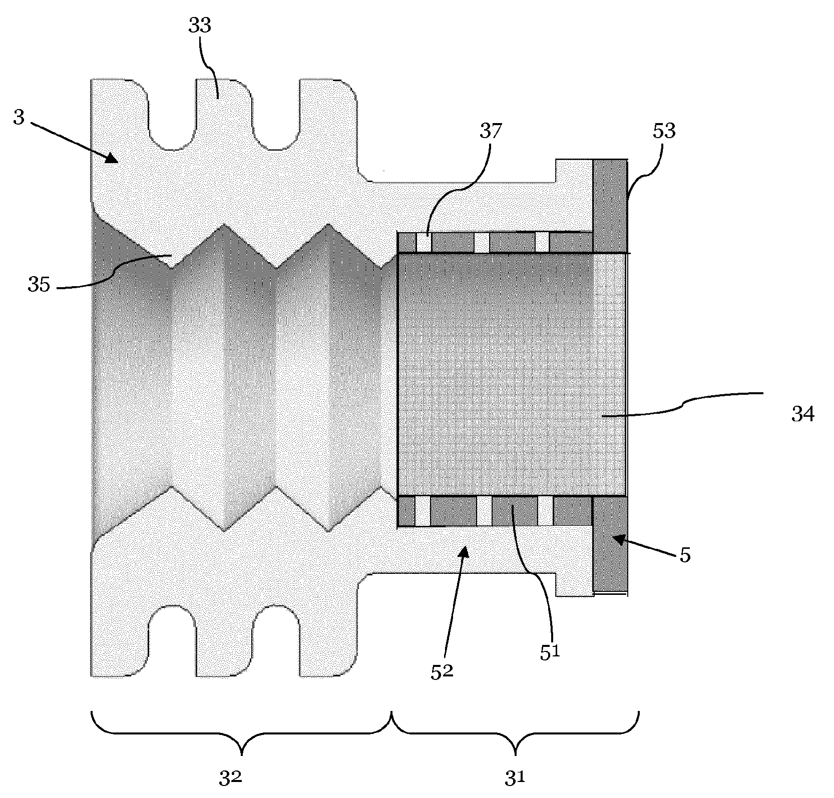
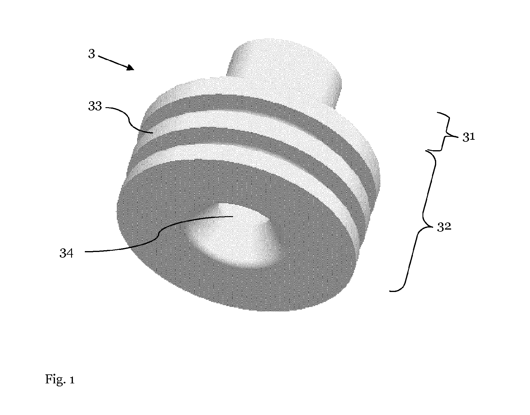
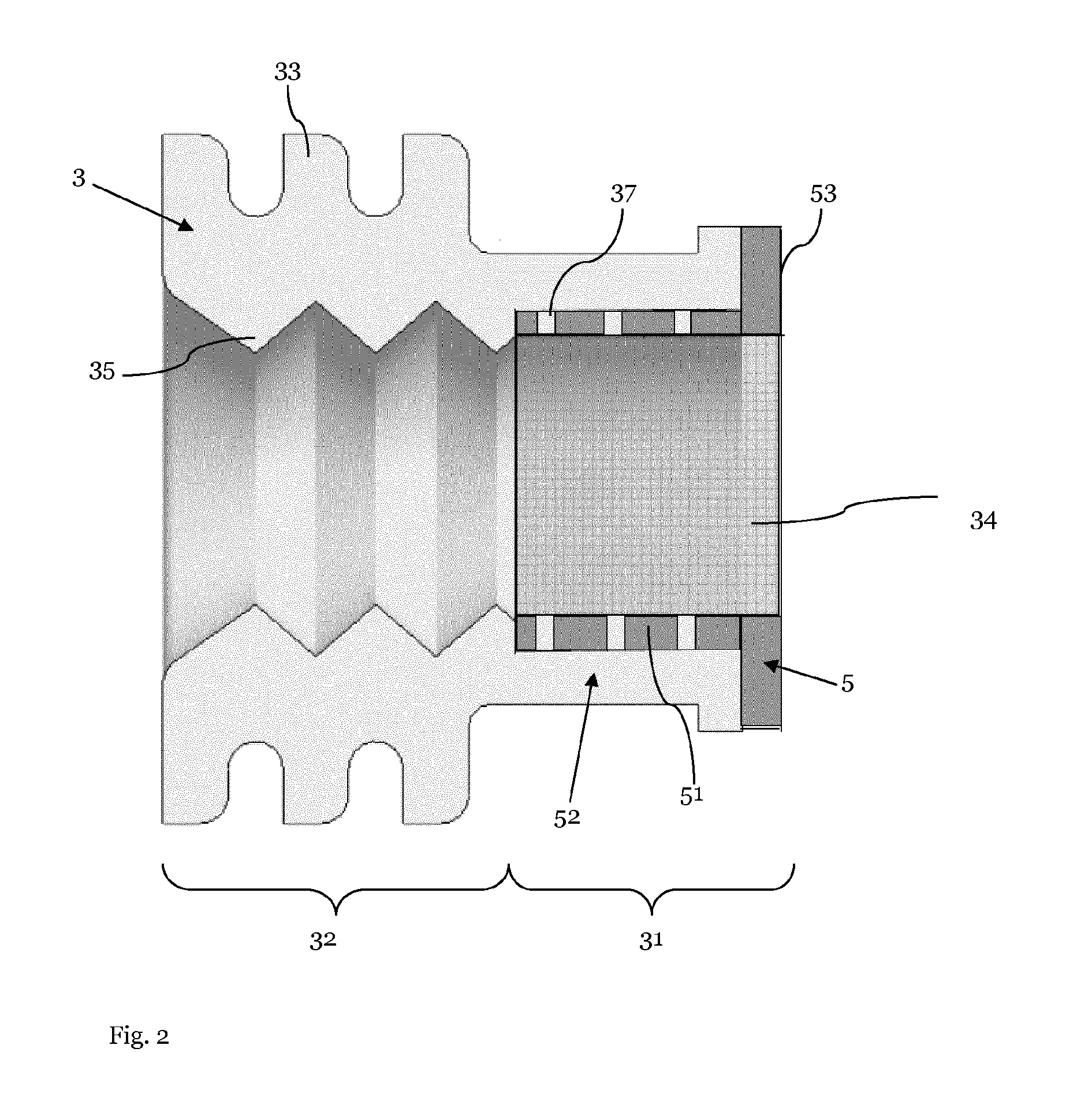
[0026]FIG. 1 shows a 3D-illustration of a single wire seal 3 to be attached to an electric cable (not shown) for sealing the electric cable in an aperture of a terminal (not shown) or a connector housing (not shown). The rotation symmetrical single wire seal 3 is provided with an essentially cylindrical shape and a through hole 34 for the electric cable. The single wire seal 3 is further provided with a crimping portion 31 and with a sealing portion 32 having an essentially smooth outer surface area with some ring-shaped sealing lips 33, extending between a smaller diameter and a la...


PUM


Abstract

A single wire seal for sealing an electric cable in an aperture of a terminal or a connector housing is provided. The single wire seal is provided with an essentially cylindrical shape and a through hole for the electric cable. The single wire seal further comprises a crimping portion for crimping the crimping section of a terminal on both the single wire seal and the electric cable. The single wire seal is molded out of a first, preferably relatively soft elastic material having a Young's modulus. For reducing deformations of the single wire seal due to the crimping, the single wire seal is further provided with a reinforcement element arranged at the crimping portion. The reinforcement element is preferably provided with at least one ring shaped portion. The reinforcement element is molded out of a second material, which has a higher Young's modulus than the first material.

Description

CROSS-REFERENCE TO RELATED APPLICATION[0001]This application is a national stage application under 35 U.S.C. §371 of PCT Application Number PCT / EP2013 / 061147 having an international filing date of May 30, 2013, which designated the United States, said PCT application claiming the benefit of PCT Application Number PCT / IB2012 / 0011198, having an international filing date of May 31, 2013, which also designated the United States, the entire disclosure of each of which are hereby incorporated herein by reference.TECHNICAL FIELD OF THE INVENTION[0002]The present invention relates to a single wire seal for seating an electric cable in an aperture of a terminal or a connector housing, and in particular to a single wire seal which is to be attached onto the electric cable.BACKGROUND OF THE INVENTION[0003]In many applications, it is necessary to mount electrical cables to terminals or connector housings and to seal the connection against moisture or dust etc. To this end so-called single wire ...

Claims


Application Information

Patent Timeline
Patent Type & Authority Patents(United States)
IPC IPC(8): H02G15/013H01R13/52H01R13/40
CPCH02G15/013H01R13/5205
Inventor MUEHLMICHEL, JURGENMATZ, KERSTINFILI, THOMAS
Owner APTIV TECH LTD
Why Eureka
Try Eureka