AI technical title is built by Patsnap AI team. It summarizes the technical point description of the patent document.
a technology of blood treatment and dialysis, which is applied in the field of hemodialysis and similar dialysis systems, can solve the problems of large amount of dialysate needed for hemodialysis, inefficient hemodialysis, difficult and expensive, etc., and achieve the effect of increasing pressur
Active Publication Date: 2016-12-13
DEKA PROD LLP
View PDF593 Cites 60 Cited by
Summary
Abstract
Description
Claims
Application Information
AI Technical Summary
This helps you quickly interpret patents by identifying the three key elements:
Problems solved by technology
Method used
Benefits of technology
Benefits of technology
The invention relates to a method for safely and quickly returning blood to a patient in an extracorporeal treatment system, in case of power loss or other interruptions. The method involves using compressed gas to increase pressure in the system to cause the blood to flow back to the patient. This is achieved by opening valves to create fluid pathways between the compressed gas, the electrolyte solution and the filter, and redirecting any excess fluid away from the filter to avoid clogging. The method is effective and reliable, providing a quick and safe solution to potential treatment system malfunctions.
Problems solved by technology
Many factors make hemodialysis inefficient, difficult, and expensive.
These factors include the complexity of hemodialysis, the safety concerns related to hemodialysis, and the very large amount of dialysate needed for hemodialysis.
Therefore any increase in the ease and efficiency of the dialysis process could have an impact on treatment cost or patient outcome.
Method used
Image
Click on the blue label to locate the original text in one second.
Reading with bidirectional positioning of images and text.
Examples
Embodiment Construction
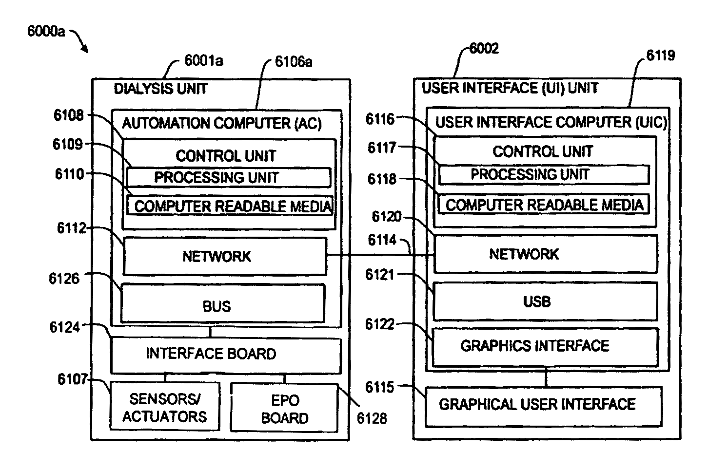
[0285]The present invention generally relates to hemodialysis and similar extracorporeal blood treatment systems, including a variety of systems and methods that would make hemodialysis more efficient, easier, and / or more affordable. One aspect of the invention is generally directed to new fluid circuits for fluid flow. In one set of embodiments, a hemodialysis system may include a blood flow path and a dialysate flow path, where the dialysate flow path includes one or more of a balancing circuit, a mixing circuit, and / or a directing circuit. Preparation of dialysate by the mixing circuit, in some instances, may be decoupled from patient dialysis. In some cases, the circuits are defined, at least partially, within one or more cassettes, optionally interconnected with conduits, pumps, or the like. In one embodiment, the fluid circuits and / or the various fluid flow paths may be at least partially isolated, spatially and / or thermally, from electrical components of the hemodialysis syst...
PUM
Abstract
Dialysis systems are disclosed comprising new fluid flow circuits. Systems may include blood and dialysate flow paths, where the dialysate flow path includes balancing, mixing, and / or directing circuits. Dialysis systems may include a safety system utilizing a field programmable gate array (FPGA) that monitors at least conductivity and temperature of dialysate in the flow circuit upstream of a dialyzer and enters a fail-safe state if the measured conductivity is outside of a range of values. The FPGA may be verified to be operating properly by exposing sensors in fluid paths to temperatures or conductivities that are outside pre-determined permissible ranges of values, and confirming that the FPGA safety system enters a fail-safe state in response to the temperatures or conductivities. The FPGA may be configured to monitor an amount of ultrafiltration fluid withdrawn from a patient during dialysis treatment and to enter a fail-safe state if a maximum amount is exceeded.
Description
RELATED APPLICATIONS[0001]This application is a continuation in part of U.S. application Ser. No. 12 / 549,285, now U.S. Pat. No. 8,409,441, entitled “Blood Treatment Systems and Methods,” filed on Aug. 27, 2009, which claims the benefit, under 35 U.S.C. §119(e), of U.S. Provisional Application Ser. No. 61 / 092,239, filed on Aug. 27, 2008, and which is a continuation in part of U.S. application Ser. No. 12 / 199,452, now U.S. Pat. No. 8,357,298, entitled “Hemodialysis Systems and Methods,” filed on Aug. 27, 2008, which is a continuation in part of U.S. application Ser. No. 12 / 072,908, now U.S. Pat. No. 8,246,826, entitled “Hemodialysis Systems and Methods,” filed on Feb. 27, 2008, which claims the benefit, under 35 U.S.C. §119(e), of U.S. Provisional Application Ser. No. 60 / 903,582, filed on Feb. 27, 2007, and which claims the benefit, under 35 U.S.C. §119(e), of U.S. Provisional Application Ser. No. 60 / 904,024, filed on Feb. 27, 2007.[0002]This application also claims the benefit, under...
Claims
Application Information
Patent Timeline
Application Date:The date an application was filed.
Publication Date:The date a patent or application was officially published.
First Publication Date:The earliest publication date of a patent with the same application number.
Issue Date:Publication date of the patent grant document.
PCT Entry Date:The Entry date of PCT National Phase.
Estimated Expiry Date:The statutory expiry date of a patent right according to the Patent Law, and it is the longest term of protection that the patent right can achieve without the termination of the patent right due to other reasons(Term extension factor has been taken into account ).
Invalid Date:Actual expiry date is based on effective date or publication date of legal transaction data of invalid patent.

