
Curling broom incorporating a motor

a technology of curling brooms and motors, applied in the field of curling brooms, can solve the problems of the game will stop, and the players who can no longer effectively sweep the rock will quit the game, and achieve the effect of minimizing the force required to be applied

Active Publication Date: 2016-12-13
IRELAND JOHN ALBERT +1
View PDF13 Cites 0 Cited by
  • Summary
  • Abstract
  • Description
  • Claims
  • Application Information

AI Technical Summary

Benefits of technology

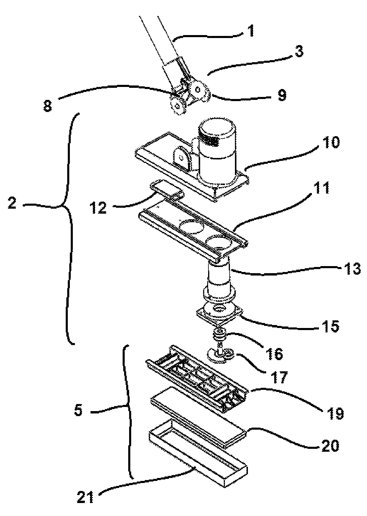
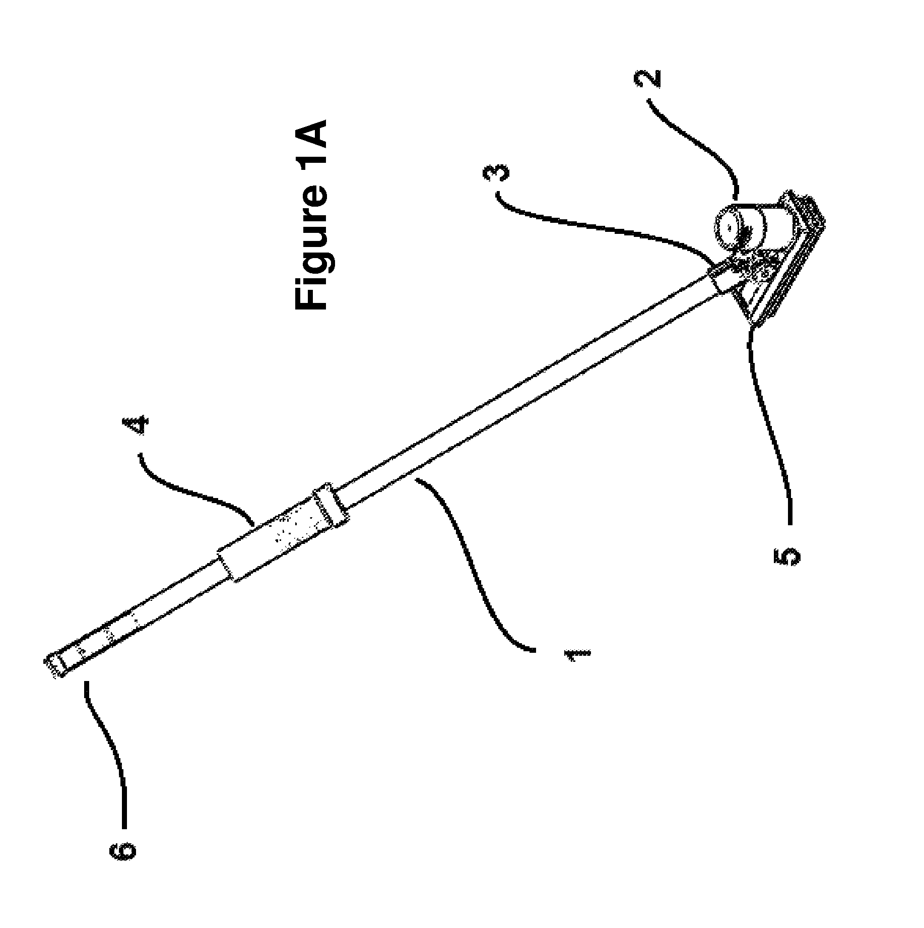
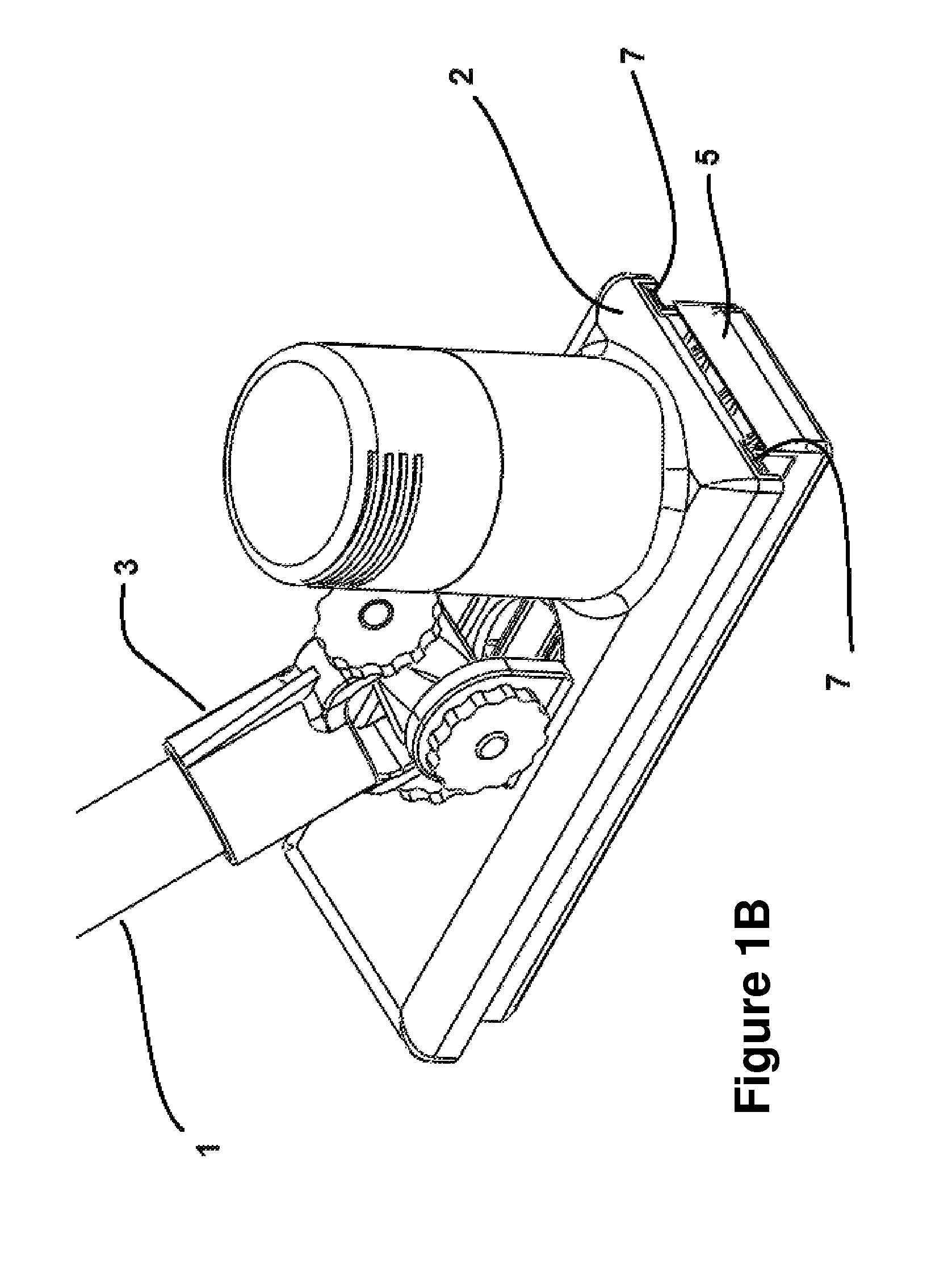
The present invention is an improved curling broom and brush head that uses a motor to cause a back and forth motion of the brush head on the ice, replacing the traditional sweeping action performed by a curler. This allows individuals who can no longer sweep effectively to still participate as an effective team member in the game. The brush head comprises a slot with two parallel surfaces that can be pushed by the motor's crank to cause the brush head to move in a sinusoidal pattern. A gear reduction element can be used to control the speed of the motor. A slide plate is also included, with a first slide element and second slide element that allows the brush head to move laterally. A counterbalance can be added to reduce vibration caused by the rotating crank. Overall, the motorized curling broom allows for smoother and more effective sweeping, making it easier for more people to join the game.

Problems solved by technology

The formation of this water layer requires a transfer of mechanical energy from the momentum of the moving rock to the surface of the ice and will therefore gradually reduce its momentum, which will eventually cause the rock to stop.
The turn or slow spin which the curler applies to the rock upon delivery results in a side to side imbalance in the rate at which the momentum of the rock is lost to this energy transfer, resulting in a net sideways force on the travelling rock and the characteristic curl in the trajectory of a delivered curling rock.
In many cases, players who can no longer effectively sweep the rock will quit the game.

Method used


Image

  • Curling broom incorporating a motor
  • Curling broom incorporating a motor
  • Curling broom incorporating a motor

Examples


Embodiment Construction

[0026]The present invention is directed to a motorized broom that may be used in the game of curling. The curling broom, according to an embodiment of the present invention, comprises a moveable synthetic fabric brush head that can provide a sweeping motion consistent with the regulatory requirements of the bodies governing the game of curling in Canada and worldwide. The present invention can allow those individuals who would otherwise not be able to effectively accomplish a sweeping motion with their own strength or stamina to participate recreationally and competitively in the game.

[0027]The curling broom, according to various embodiments of the present invention, comprises: a motor and associated gear reduction and crank configuration for causing a sinusoidal back and forth sweeping action of the brush head; a power source such as an electrical battery that may be replaceable and / or rechargeable for providing power to the motor; a user control mechanism for intuitive adjustment ...


PUM


Abstract

A motorized broom that may be used in the game of curling is provided. The broom comprises a moveable synthetic fabric brush head that can provide a sweeping motion consistent with the regulatory requirements governing the game of curling. The motorized curling broom can assist individuals who would otherwise not be able to effectively accomplish a sweeping motion with their own strength or stamina to participate recreationally and competitively in the game. The curling broom comprises: a motor and associated gear reduction and crank configuration for causing a sinusoidal back and forth sweeping action of the brush head. The broom further includes a user control mechanism for intuitive adjustment of the power supplied to the brush head by way of controlling the speed of the motor and the pressure applied to the sweeping surface. A dynamic balancing mechanism reduces unwanted vibration transmitted to the individual using the broom.

Description

CROSS-REFERENCE TO RELATED APPLICATION[0001]The present application claims the benefit under 35 USC 119(e) of U.S. Provisional Patent Application 61 / 931,553 filed on Jan. 24, 2014 and hereby incorporated by reference herein.FIELD OF THE INVENTION[0002]The invention relates generally to brooms and, more particularly, to curling brooms incorporating a motor.BACKGROUND[0003]Brooms used in the game of curling can be used by a curler to significantly modify the slide distance and trajectory of a delivered curling rock. It is known that when any object moves by itself or is encouraged to move across the surface of an ice sheet, that it does so by forming a thin layer of water between the moving object and the solid surface of the ice. In the case of a curling rock, this layer of water, which forms between the running ring on the underside of the granite body of the rock and the top surfaces of the pebbles or tiny bumps applied to the surface of a curling ice sheet during the ice making pr...

Claims


Application Information

Patent Timeline
Patent Type & Authority Patents(United States)
IPC IPC(8): A63B67/14A46B13/02A63B71/06
CPCA63B67/148A46B13/02A46B2200/308A63B71/0619
Inventor IRELAND, JOHN ALBERTIRELAND, ALEXANDER JOHN
Owner IRELAND JOHN ALBERT
Learn More