Clamping structure for open end wrench

a technology of open end wrench and clamping structure, which is applied in the direction of wrenches, manufacturing tools, spanners, etc., to achieve the effect of small operating space and easy operation

Active Publication Date: 2016-12-20
YUNG FONG TOOLS
View PDF15 Cites 2 Cited by
  • Summary
  • Abstract
  • Description
  • Claims
  • Application Information

AI Technical Summary

Benefits of technology

[0005]The primary object of the present invention is to provide a clamping structure for an open end wrench which rotates a workpiece in a small operating space easily.

Problems solved by technology

However, the body is rotated repeatedly between a rotatable starting point and a rotatable stopping point to rotating the hex nut troublesomely.

Method used


Image

  • Clamping structure for open end wrench
  • Clamping structure for open end wrench
  • Clamping structure for open end wrench

Examples


Embodiment Construction

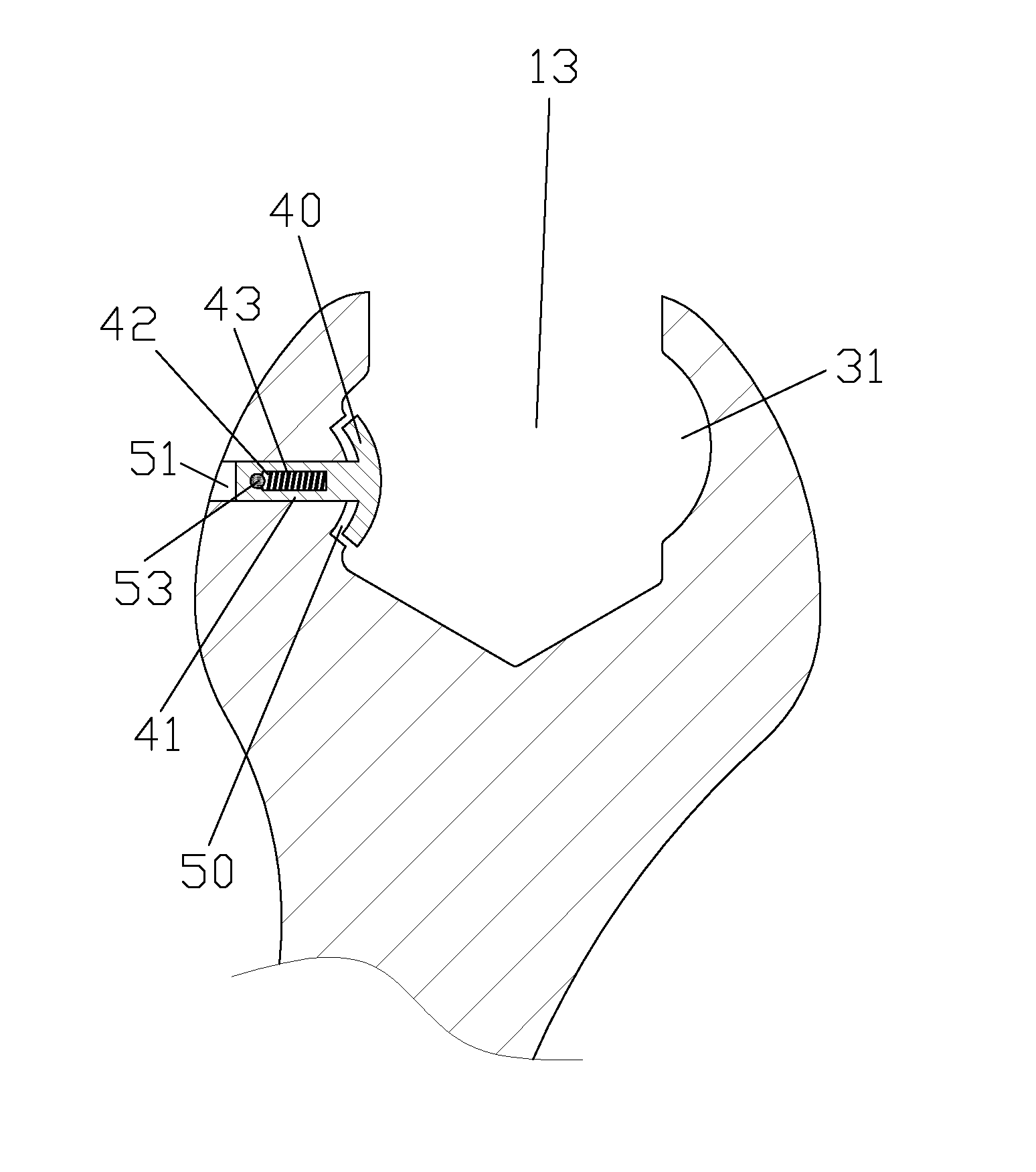
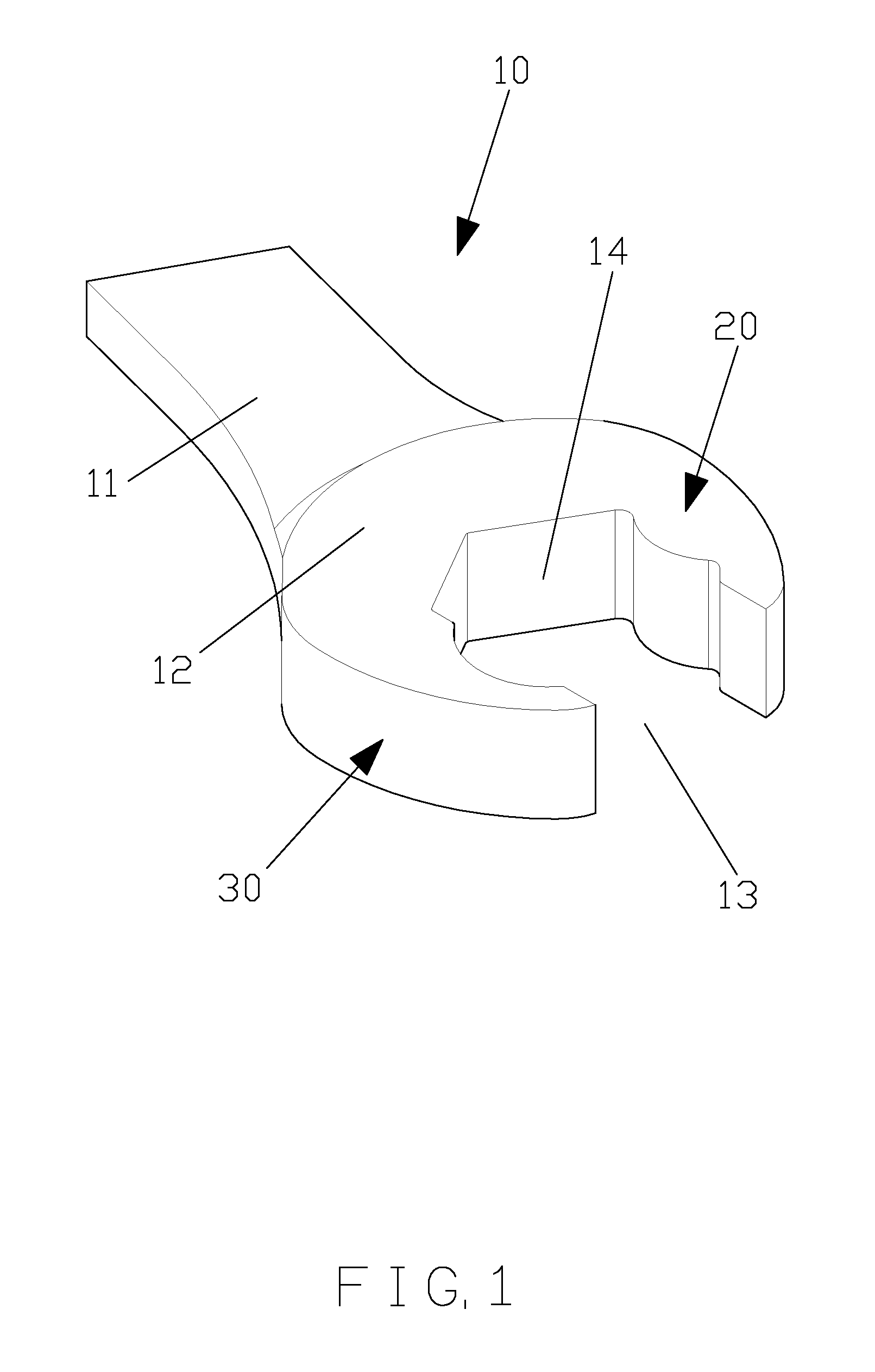
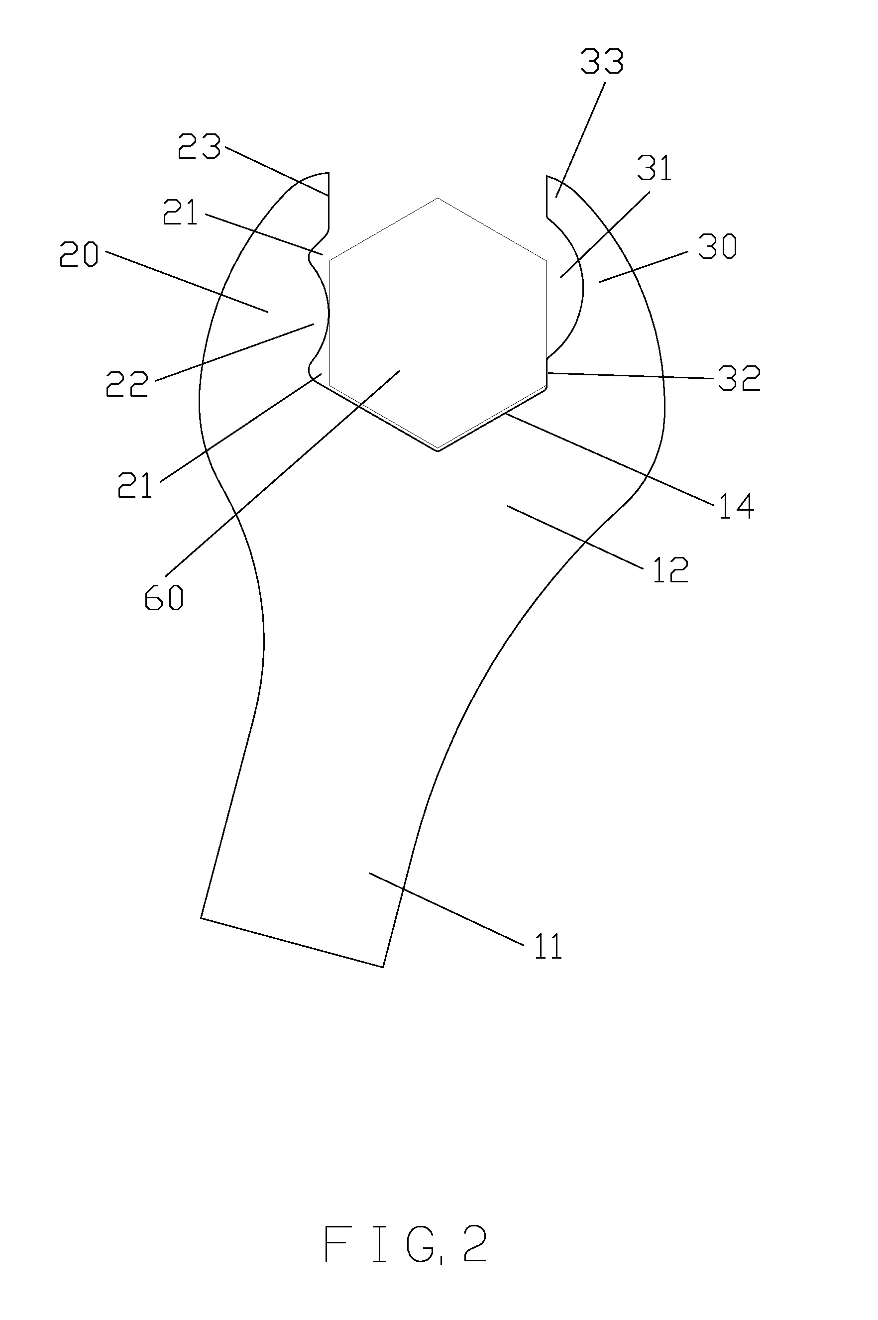
[0030]Referring to FIGS. 1 and 2, a clamping structure for an open end wrench according to a first embodiment of the present invention comprises: a body 10, and the body 10 includes a handle 11, an operation head 12 connecting with a front end of the handle 11, and a clamping portion 13 defined thereon; wherein the clamping portion 13 has a first jaw 20 arranged on a first side thereof, a second jaw 30 formed on a second side thereof, and a V-shaped retaining fringe 14 defined on a rear end thereof; the first jaw 20 has a first plane 23 defined on a front end thereof, two first recesses 21 arranged on a rear end of the first plane 23 and a first front end of the V-shaped retaining fringe 14, and an arcuate projection 22 defined between the two first recesses 21; the second jaw 30 has a second plane 33 defined on a front end thereof, an abutting face 32 arranged between a rear end thereof and a second front end of the V-shaped retaining fringe 14, and an arcuately concaved section 31...


PUM


Abstract

A clamping structure for an open end wrench contains: a body, and the body including a handle, an operation head, and a clamping portion. The clamping portion has a first jaw arranged on a first side thereof, a second jaw formed on a second side thereof, and a V-shaped retaining fringe defined on a rear end thereof. The first jaw has a first plane defined on a front end thereof, two first recesses arranged on a rear end of the first plane and a first front end of the V-shaped retaining fringe, and an arcuate projection defined between the two first recesses. The second jaw has a second plane defined on a front end thereof, an abutting face arranged between a rear end thereof and a second front end of the V-shaped retaining fringe, and an arcuately concaved section formed between the second plane and the abutting face.

Description

FIELD OF THE INVENTION[0001]The present invention relates to a clamping structure for an open end wrench which rotates a workpiece in a small operating space easily.BACKGROUND OF THE INVENTION[0002]A conventional open end wrench is employed to rotate a hex nut and contains a clamping portion, and the clamping portion has two retaining sections defined on two sides thereof to retain two of six sides of the hex nut and to rotate the hex nut.[0003]However, the body is rotated repeatedly between a rotatable starting point and a rotatable stopping point to rotating the hex nut troublesomely.[0004]The present invention has arisen to mitigate and / or obviate the afore-described disadvantages.SUMMARY OF THE INVENTION[0005]The primary object of the present invention is to provide a clamping structure for an open end wrench which rotates a workpiece in a small operating space easily.[0006]To obtain the above object, a clamping structure for an open end wrench provided by the present invention ...

Claims


Application Information

Patent Timeline
Patent Type & Authority Patents(United States)
IPC IPC(8): B25B13/08B25B13/46
CPCB25B13/08B25B13/46
Inventor CHEN, TZU-CHUN
Owner YUNG FONG TOOLS
Why Eureka
Try Eureka