Dynamic monitoring device for danger of rotary kiln and monitoring method

A dynamic monitoring and rotary kiln technology, applied in the field of rotary kiln, can solve the problems of occupying operating space, high installation and maintenance costs, cumbersome and other problems, and achieve the effect of occupying small operating space, simple monitoring method and broad market prospect

Active Publication Date: 2018-08-10
ZHONGYE-CHANGTIAN INT ENG CO LTD
View PDF6 Cites 2 Cited by
  • Summary
  • Abstract
  • Description
  • Claims
  • Application Information

AI Technical Summary

Problems solved by technology

[0006] 1. The monitoring range is small and the installation cost is high: the existing technology can only monitor the surface temperature value of a small part of the area of ​​the rotary kiln. The safety factor brings great hidden dangers to the personal safety of operators
However, if temperature measuring devices are installed at multiple points of the rotary kiln, the installation and maintenance costs will be too high, which will seriously affect the economics of production
[0007] 2. It is impossible to predict the location of furnace lining peeling off: due to the inability to fully scan the kiln body covering the entire rotary kiln, it is impossible to physically model the various positions and areas on the rotary kiln body in the prior art, so that even when the temperature measuring device detects the temperature When the value changes, it is impossible to predict the corresponding location of furnace lining peeling, and it is also impossible to give a reference repair suggestion, which leads to the operator having to find the high temperature point of furnace lining peeling one by one in the whole kiln body, which is cumbersome and increases labor. strength
[0009] 1. The monitoring range is small: in the existing technology, a CO detector is generally installed at a certain point on the valve group platform of the rotary kiln. This method can only monitor the relevant parameters of a small part of the valve group platform of the rotary kiln. The monitoring range is very small and cannot Reflecting the real situation will reduce the safety factor of the rotary kiln valve group platform and bring great hidden dangers to the personal safety of operators
However, if CO detectors are installed at multiple points on the rotary kiln valve group platform, the cost will be too high and the operating space of the rotary kiln will be greatly reduced
[0010] 2. Occupy the operating space of the valve group platform of the rotary kiln: the CO detector needs to be connected with the signal cable and the power cable to operate normally, and the cable needs to be covered with steel pipes. During operation, it is very easy to trip over the cable jacket steel pipe and cause production accidents
[0011] 3. Unable to predict the location of CO leakage: under the existing technology, when the CO detector detects CO leakage, the system cannot predict the location of CO leakage
If you want to know the CO leakage point, the operator has to take a portable CO detector to test the location one by one, which is cumbersome and increases the labor intensity

Method used


Image

  • Dynamic monitoring device for danger of rotary kiln and monitoring method
  • Dynamic monitoring device for danger of rotary kiln and monitoring method
  • Dynamic monitoring device for danger of rotary kiln and monitoring method

Examples


Embodiment 1

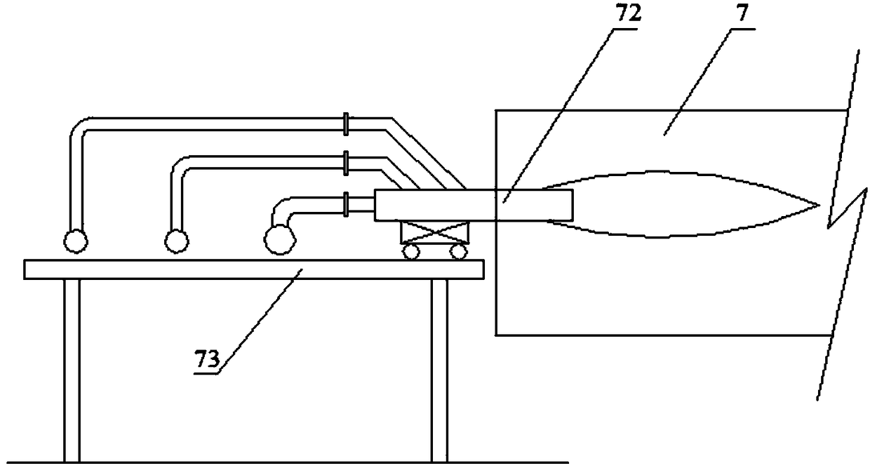
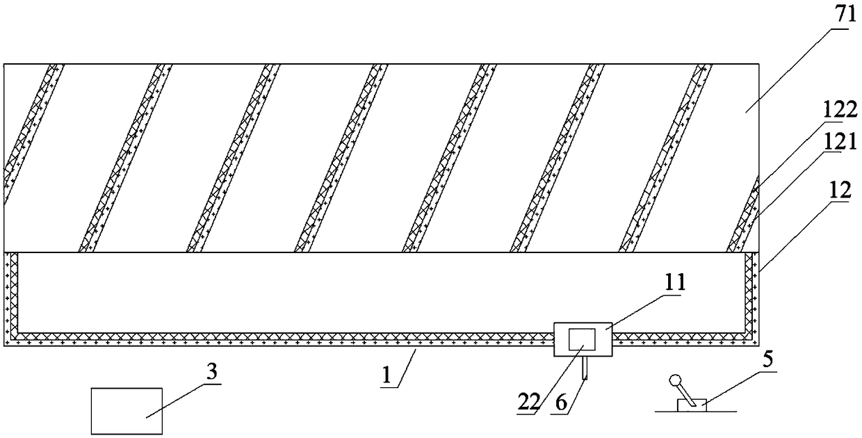
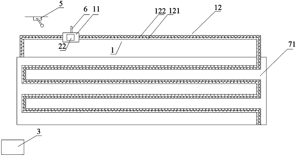
[0049] Such as figure 1 , Figure 5 As shown, the dynamic monitoring device for the peeling off of the rotary kiln 7 furnace lining in this embodiment, the rotary kiln 7 includes a kiln body 71, a burner device for heating the kiln body 71 and a drive device for driving the kiln body 71 to rotate, the burner device includes a central A burner 72 and a valve group platform 73 for supplying fuel to the central burner 72 . The dynamic monitoring device includes a patrol device 1, a temperature detector 22 and a controller 3. The patrol device 1 includes a patrol robot 11, a drive device (including a drive motor and a walking wheel 26) and a track 12 arranged around the kiln body 71, and the temperature detector 22 is installed on the patrol robot 11, and the patrol robot 11 runs on the track 12 driven by the driving device, and the temperature detector 22 transmits the monitoring signals received around the kiln body 71 to the controller 3 in real time.

[0050] In this embodim...

Embodiment 2

[0067] Such as figure 1 , Figure 5 As shown, the dynamic monitoring device for CO leakage of the rotary kiln 7 valve group platform 73 in this embodiment, the rotary kiln 7 includes a kiln body 71, a burner device for heating the kiln body 71 and a driving device for driving the kiln body 71 to rotate, the burner The device includes a central burner 72 and a valve group platform 73 for supplying fuel to the central burner 72 . The dynamic monitoring device includes a patrol device 1, a CO detector 21 and a controller 3. The patrol device 1 includes a patrol robot 11, a driving device (including a driving motor and a traveling wheel 26) and a track 12 arranged on the upper part of the valve group platform 73, and the CO detection The instrument 21 is installed on the patrol robot 11, and the patrol robot 11 runs on the track 12 driven by the driving device. The CO detector 21 transmits the monitoring signal received on the upper part of the valve group platform 73 to the cont...


PUM


Abstract

The invention discloses a dynamic monitoring device for danger of a rotary kiln. The rotary kiln comprises a kiln body, a burner device for supplying heat for the kiln body and a driving device for driving the kiln body to rotate, the burner device comprises a central burner and a valve bank platform used for providing fuel to the central burner, the dynamic monitoring device comprises a patrol device, a detector and a controller, the patrol device comprises a patrol robot, a driving device and a track arranged at the danger-to-be-monitored position of the rotary kiln, the detector is installed on the patrol robot, the patrol robot runs on the track under driving of the driving device, and the detector transmits the monitoring signal received at the to-be-monitored-position to the controller in real time. The invention further provides a monitoring method of the dynamic monitoring device correspondingly. The dynamic monitoring device is large in monitoring range, small in occupied operating space, simple and convenient in monitoring method and high in monitoring efficiency.

Description

technical field [0001] The invention belongs to the field of rotary kilns, and in particular relates to a dynamic monitoring device and a monitoring method for dangerous situations of a rotary kiln. Background technique [0002] Rotary kiln, also known as rotary calcining kiln, is a large-scale equipment in the core industry, which is widely used in building materials, metallurgy, chemical industry, environmental protection and other production industries. Its function is to use rotation and internal high temperature to calcine the materials in the kiln to form finished ore. Rotary kiln can be divided into cement kiln, metallurgical chemical kiln and lime kiln according to different materials. Cement kilns are mainly used for calcining cement clinker, which can be divided into two categories: dry production cement kiln and wet production cement kiln. Metallurgical and chemical kilns are mainly used for magnetization roasting of lean iron ore in iron and steel plants, oxida...

Claims


Application Information

Patent Timeline
Patent Type & Authority Applications(China)
IPC IPC(8): F27B7/42F27D21/00
CPCF27B7/42F27D21/00F27D2021/0057
Inventor 周浩宇向锡炎刘前
Owner ZHONGYE-CHANGTIAN INT ENG CO LTD
Why Eureka
Try Eureka