Micro collimator system and method for a head up display (HUD)

Active Publication Date: 2016-12-20
ROCKWELL COLLINS INC
View PDF566 Cites 102 Cited by
  • Summary
  • Abstract
  • Description
  • Claims
  • Application Information

AI Technical Summary

Benefits of technology

[0010]In a further aspect, embodiments of the inventive concepts disclosed herein relate to a head up display. The head up display includes an image source, an illuminator, a field lens arranged to receive light directly from the image source, a polarizing beam splitter having a first face, a second face, a third face, and a fourth face, a retarder disposed to receive the light provided through the second face, and a curved reflector. The field lens has a diffractive surface for providing color correction and having a higher order of aberration control, and the illuminator is arranged to illuminate the image source through the polarizing beam splitter through the fourth face and the first face. The light from the illuminator entering the fourth f

Problems solved by technology

Conventional HUDs are generally large, expensive and difficult to fit into smaller aircraft, such as, business and regional jets as well as general aviation airplanes.
The volume of the packages including the optical components of the HUD is too large to fit within the constrained space in the cockpit of smaller aircraft.
Further, conventional HUD

Method used


Image

  • Micro collimator system and method for a head up display (HUD)
  • Micro collimator system and method for a head up display (HUD)
  • Micro collimator system and method for a head up display (HUD)

Examples


Embodiment Construction

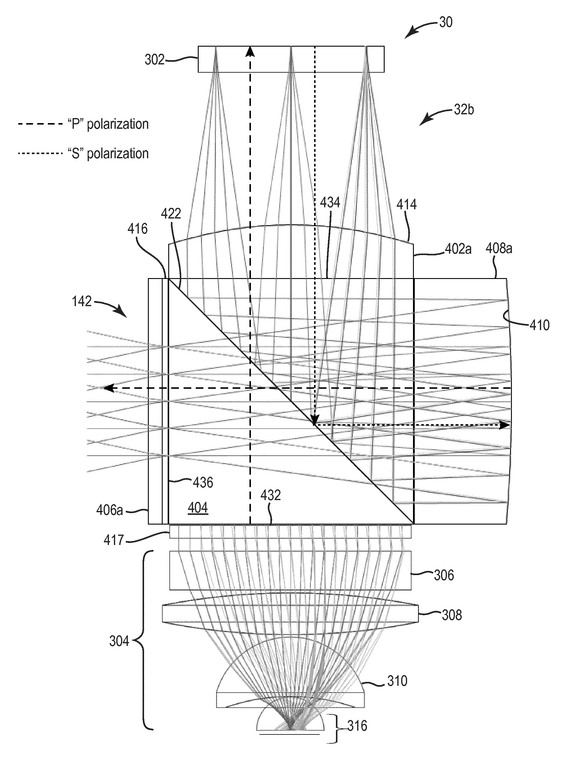
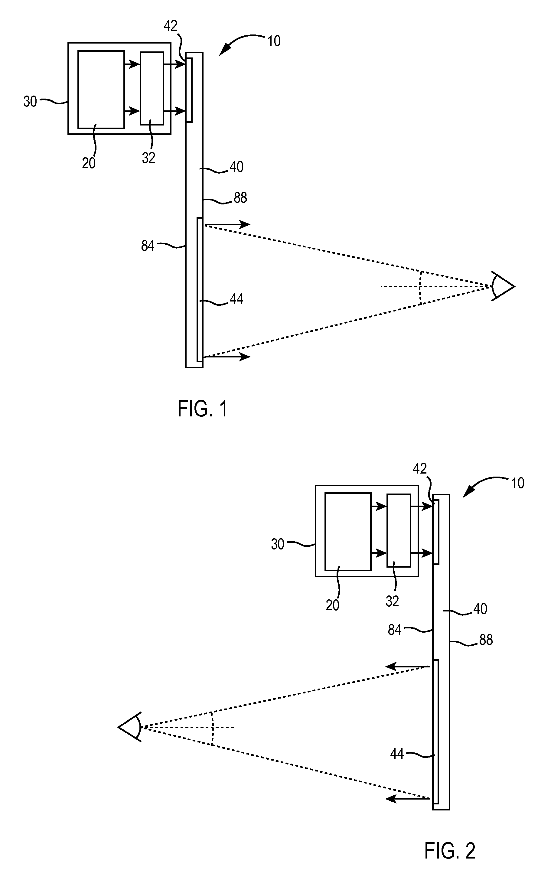
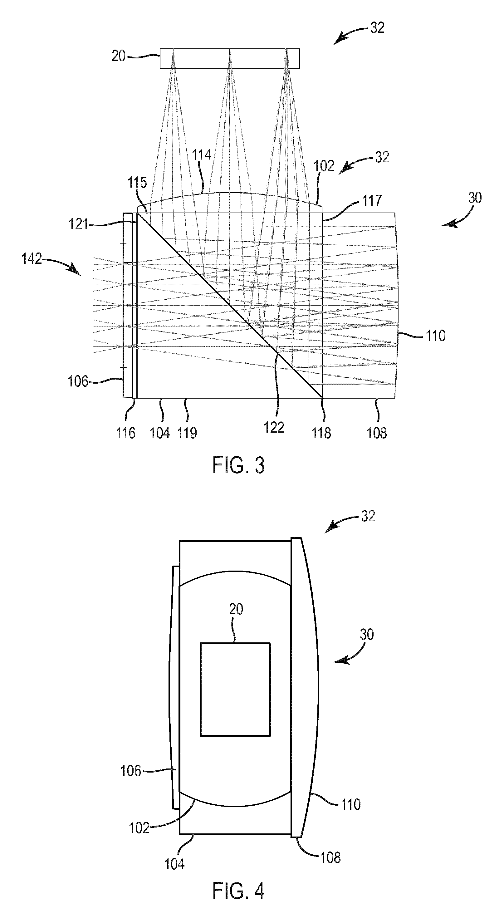
[0031]Before describing in detail the particular improved system and method, it should be observed that the inventive concepts disclosed herein include, but are not limited to, a novel structural combination of optical components and not in the particular detailed configurations thereof. Accordingly, the structure, methods, functions, control and arrangement of components have been illustrated in the drawings by readily understandable block representations and schematic drawings, in order not to obscure the disclosure with structural details which will be readily apparent to those skilled in the art, having the benefit of the description herein. Further, the inventive concepts disclosed herein are not limited to the particular embodiments depicted in the exemplary diagrams, but should be construed in accordance with the language in the claims.

[0032]In some embodiments, a collimator advantageously includes a field lens and a reflector mounted onto a cube, thereby allowing easy mechan...


PUM


Abstract

A head up display can use a catadioptric collimating system. The head up display includes an image source. The head up display also includes a collimating mirror, and a polarizing beam splitter. The light from the image source enters the beam splitter and is reflected toward the collimating mirror. The light striking the collimating mirror is reflected through the beam splitter toward a combiner. A field lens can include a diffractive surface. A corrector lens can be disposed after the beam splitter.

Description

CROSS REFERENCE TO RELATED APPLICATIONS[0001]The present application is related to U.S. patent application Ser. No. 13 / 432,662 filed on Mar. 28, 2012 entitled “System For And Method of Catadioptric Collimation In A Compact Head Up Display (HUD),” incorporated herein by reference in its entirety and assigned to the assignee of the present application which a continuation-in-part application of: U.S. Pat. No. 8,634,139 filed on Sep. 30, 2011 entitled “System For And Method of Catadioptric Collimation In A Compact Head Up Display (HUD),” incorporated herein by reference in its entirety and assigned to the assignee of the present application; “U.S. patent application Ser. No. 13 / 250,940, entitled, “Head Up Display (HUD) Utilizing Diffractive Gratings Having Optimized Efficiency,” filed on Sep. 30, 2011, incorporated herein by reference in its entirety, and assigned to the assignee of the present application; U.S. patent application Ser. No. 13 / 250,858, entitled, “Ultra-Compact HUD Utili...

Claims


Application Information

Patent Timeline
IPC IPC(8): G02B6/00G02B17/08G02B27/01G02B27/28G02B27/00G02B27/30G02B27/42
CPCG02B27/0101G02B17/0884G02B27/283G02B27/30G02B27/4211G02B27/0081G02B2027/0178G02B2027/011G02B2027/0123G02B5/30G02B2027/015
Inventor BROWN, ROBERT D.STRATTON, ERIC P.MICKA, CHARLES W.
Owner ROCKWELL COLLINS INC
Why Eureka
Try Eureka