System and method for decoding block of data received over communication channel

a technology of communication channel and decoding block, applied in the field of digital communication, can solve the problems of high data rate mimo system, high computational complexity, and difficult placement of hundreds of antennas, and achieve the effect of reducing complexity

Active Publication Date: 2016-12-20
MITSUBISHI ELECTRIC RES LAB INC
View PDF10 Cites 0 Cited by
  • Summary
  • Abstract
  • Description
  • Claims
  • Application Information

AI Technical Summary

Benefits of technology

[0007]The channel variation over a single block of symbols transmitted on a doubly selective channel is not negligible due to both ICI and ISI. Maximum Likelihood Detection (MLD) is unfeasible in high data rate MIMO systems. Several detection methods can achieve near-MLD performance. For example, QR decomposition with M-algorithm, i.e., a QRD-M method, reduces the complexity by selecting M candidates with the smallest accumulated metrics at each level of the tree search.
[0009]Some embodiments of the invention are based on a recognition that for different sizes of the blocks of data transmitted over multiple communication channels different types of detectors can be more optimal than the others, especially considering limiting computational resources of the receivers. For example, for the block of one size to be detected by a receiver of predetermined computational power, the QRD-M can be more optimal than the LAS. The size of the small block and the value of M are governed by the computational power of a decoder. With the increase of the size of the block, the LAS method can become more optimal.

Problems solved by technology

Maximum Likelihood Detection (MLD) is unfeasible in high data rate MIMO systems.
However, to achieve near-MLD performance for a QRD-M algorithm, M should be made large, thereby necessitating higher computational complexity, which is undesirable.
Placing hundreds of antennas can be difficult in communication terminals that have space constraints.
In addition, the LAS method performs well only for relatively large blocks of transmitted data.

Method used


Image

  • System and method for decoding block of data received over communication channel
  • System and method for decoding block of data received over communication channel
  • System and method for decoding block of data received over communication channel

Examples


Embodiment Construction

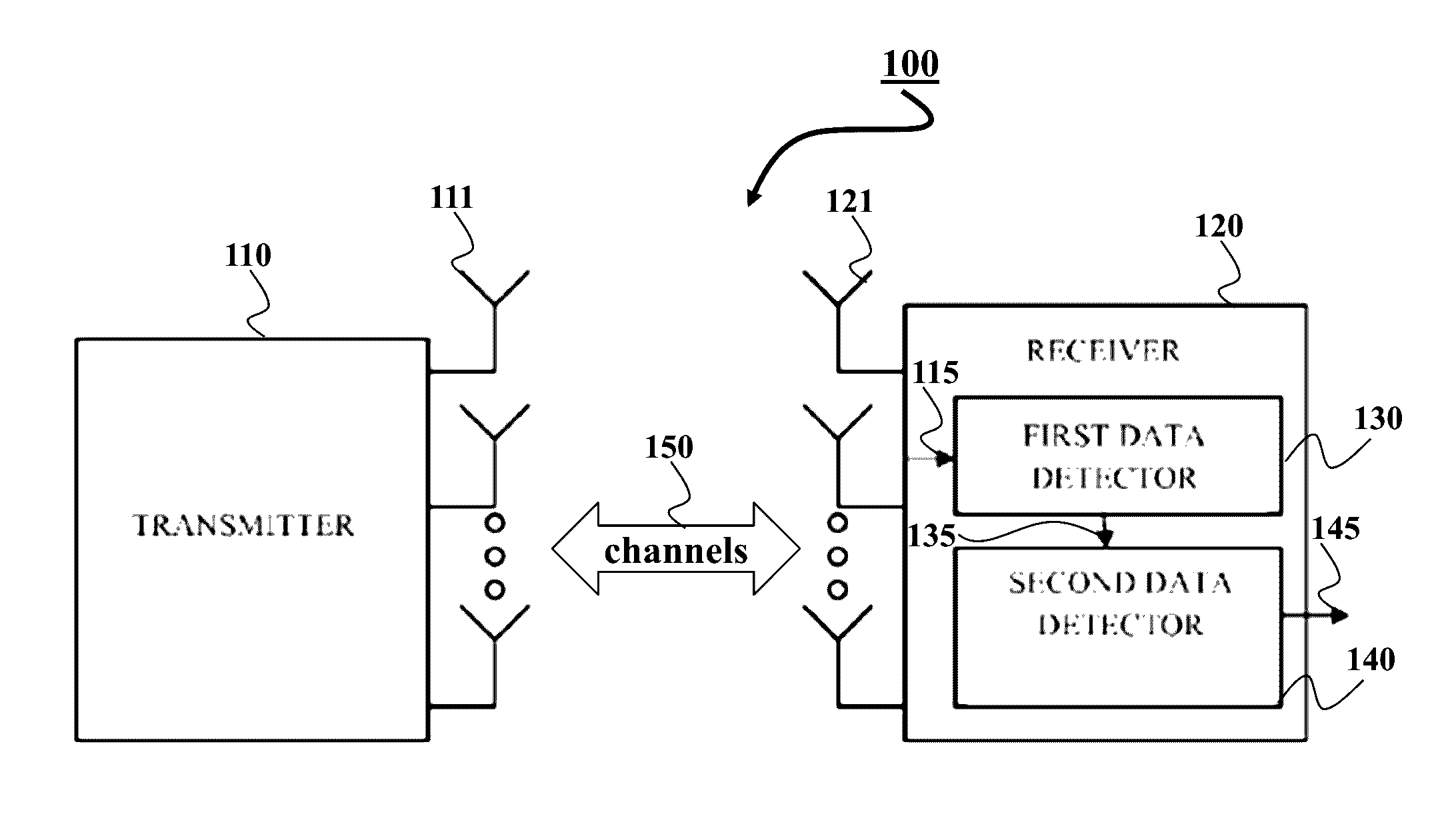
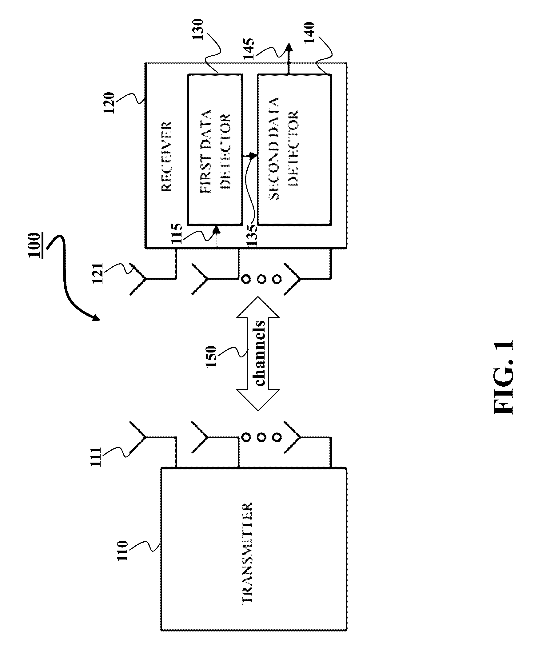
[0024]FIG. 1 shows a schematic of a system 100 employing some embodiments of the invention. The system 100 includes a transmitter 110 and a receiver 120 communicating via channels 150. The system can be a multiple-input multiple-output (MIMO) system, in which the transmitter and / or the receivers use one or multiple antennas 111, 121. Both the transmitter and the receiver can include processors and memory for processing transmitted data, and at least one RF chain connected to the antennas.

[0025]The MIMO system can increase transmission capacity of the channels 150 in proportion to the number of antennas without allocating additional frequency or transmission power, as compared to a system using a single antenna. However, some embodiments of the invention consider a point-to-point communication system with a single antenna at the transmitter and receiver.

[0026]Some embodiments are based on a general realization that block of the data transmitted over a communication channel can be bet...


PUM


Abstract

A method decodes a block of data received over a communication channel. The method determines an initial estimate of bits in the block using a QR decomposition (QRD-M) method decoding the bits in the block sequentially by reducing an accumulated distance between the initial estimate and the bits of the block. Then, the method determines the block using a likelihood ascent (LAS) method that iteratively updates the bits of the block starting from the initial estimate.

Description

FIELD OF THE INVENTION[0001]This invention relates generally to digital communications, and more particularly to decoding block of data received over communication channel.BACKGROUND OF THE INVENTION[0002]A multiple-input multiple-output (MIMO) system uses multiple transmit and receive antennas. The MIMO system can increase channel transmission capacity in proportion to the number of antennas without allocating additional frequency or transmission power, as compared to a system using a single antenna. The channel capacity of the MIMO system mainly depends on a signal detecting method used in a receiver in order to recover blocks of transmitted symbols. It is important to design the signal detecting method of the MIMO system so that high performance, low complexity and detection delay are achieved. This is a particular problem for doubly-selective channels that are subject to time-varying fading and multi-path delays, where both inter-carrier interference (ICI) and inter-symbol inter...

Claims


Application Information

Patent Timeline
Patent Type & Authority Patents(United States)
IPC IPC(8): H04L27/08H01Q11/12H04L1/00H04B7/04H03C3/40H04L25/02H04L25/03
CPCH04L1/0054H03C3/40H04B7/0413H04L25/03286H04L25/0246H04L25/03216H04L25/03891
Inventor KIM, KYEONG JINORLIK, PHILIPKOIKE-AKINO, TOSHIAKI
Owner MITSUBISHI ELECTRIC RES LAB INC
Why Eureka
Try Eureka