
Propulsion system for a vessel

a technology for propulsion systems and vessels, applied in the direction of marine propulsion, propulsive elements, vessel construction, etc., can solve the problems of reducing the cargo capacity of the vessel, increasing the cost and maintenance requirements of this type of propulsion systems, and the propulsion system is difficult to retrofit to the hull, etc., to achieve the effect of cost saving and easy removal from the hull

Active Publication Date: 2016-12-27
CATERPILLAR PROPULSION PRODION
View PDF20 Cites 1 Cited by
  • Summary
  • Abstract
  • Description
  • Claims
  • Application Information

AI Technical Summary

Benefits of technology

The invention provides a simple, reliable, and compact propulsion system. Specifically, a preferred embodiment of the invention avoids the issues that arise when operating azimuth thrusters in harsh or icy conditions for long periods of time. Another advantage is that the thrusters are easily removed from the hull.

Problems solved by technology

However the prime mover and propeller shaft require a substantial amount of space within the vessel's hull and thus diminish the cargo capacity of the vessel.
Further, the propeller shaft, which needs to be fairly long in order to extend from the inside of the hull to the outside of the hull, must be supported by several bearings, which increases the cost and maintenance requirements of this type of propulsion system.
Due to the space required, this propulsion system is very difficult to retrofit to a hull.
However, the system is vulnerable due to mechanical complexity.
Also vessels operating in ice observe problems, unless the thrusters are very much designed for this special purpose only.
In case of breakdown or major maintenance, docking of the vessel is often required because many of the components of the propulsion system, for example the angle gear and sealings, are in fact not accessible for repair or service while at sea.
This is a problem in the offshore industry where supply vessels and service vessels are very costly to take out of service outside the normal docking.

Method used


Image

  • Propulsion system for a vessel
  • Propulsion system for a vessel
  • Propulsion system for a vessel

Examples


Embodiment Construction

[0068]In the below description, one or more subscript roman numerals added to a reference number indicates that the element referred to is a further one of the element designated the un-subscripted reference number.

[0069]Further, a superscript roman numeral added to a reference number indicates that the element referred to has the same or similar function as the element designated the un-superscripted reference number, however, differing in structure.

[0070]When further embodiments of the invention are shown in the figures, the elements which are new in relation to earlier shown embodiments have new reference numbers, while elements previously shown are referenced as stated above. Elements which are identical in the different embodiments have been given the same reference numerals and no further explanations of these elements will be given.

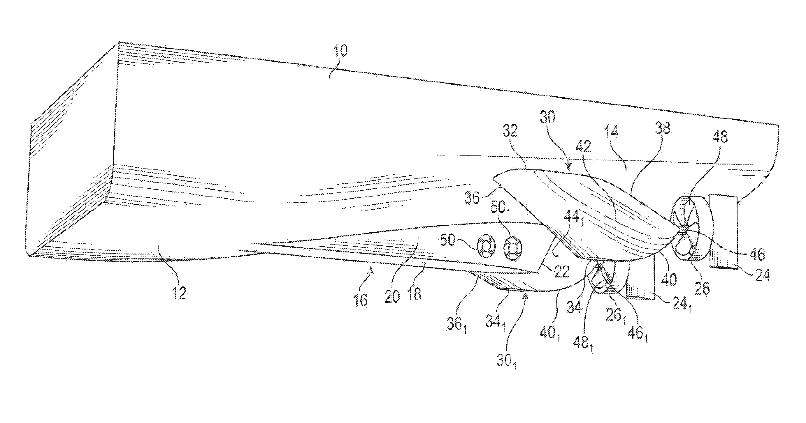
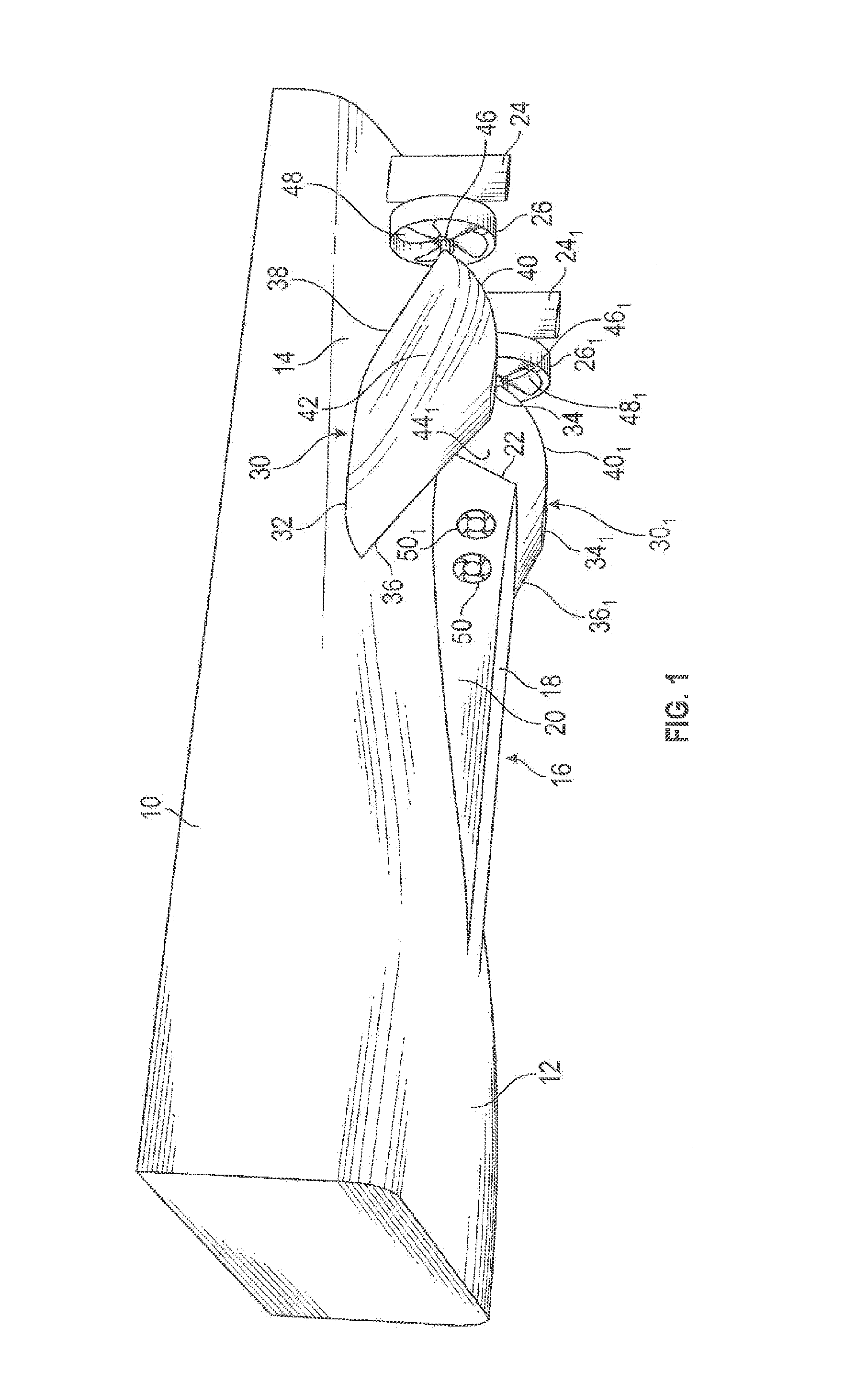
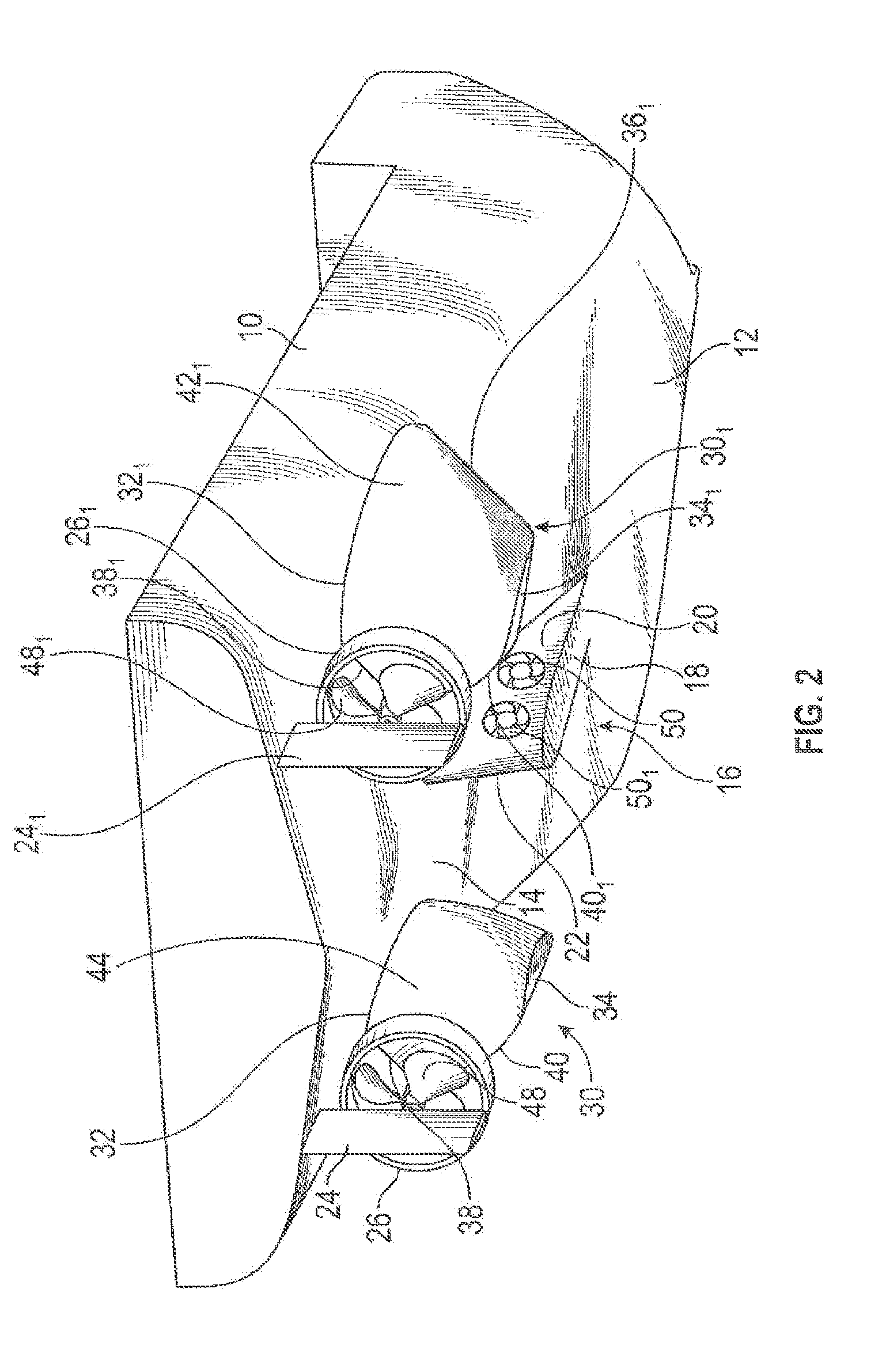
[0071]FIGS. 1 and 2 show, in perspective and partial cutaway view, a vessel's hull 10 equipped with the preferred embodiment of a propulsion syste...


PUM

PropertyMeasurementUnit
angleaaaaaaaaaa
angleaaaaaaaaaa
lengthaaaaaaaaaa

Abstract

The present invention provides a propulsion system for a vessel such as a service vessel or supply vessel. The vessel has a hull with a midship portion and a stern portion. The propulsion system comprises two propulsion units fixedly mounted to the hull on opposite sides of a centre line of the hull at the stern portion, each of the propulsion units comprising a housing carrying a propeller externally of the housing. The housing further defines an interior volume in which a drive machinery is provided for driving the propeller via a propeller shaft, the interior volume being open to the interior of the hull. A vessel comprising the propulsion system and a method of retrofitting a hull with the propulsion system are also provided.

Description

CROSS-REFERENCE TO RELATED APPLICATIONS[0001]This application is a National Stage of International Patent Application No. PCT / IB2013 / 050828, filed Jan. 31, 2013 the content of which is incorporated herein by reference in its entirety.TECHNICAL FIELD[0002]The present invention relates to a propulsion system for a vessel, the propulsion system comprising two propulsion units mounted to the vessel's hull.BACKGROUND[0003]In typical conventional propulsion systems a prime mover, for example a main engine, inside a vessel's hull provides power, either directly or by driving a generator supplying electrical power to an electric motor, to a propeller shaft extending from the inside of the hull, through the hull, to a propeller mounted on the shaft outside the hull. This type of propulsion is reliable. However the prime mover and propeller shaft require a substantial amount of space within the vessel's hull and thus diminish the cargo capacity of the vessel. Further, the propeller shaft, whi...

Claims


Application Information

Patent Timeline
Patent Type & Authority Patents(United States)
IPC IPC(8): B63H21/17B63B3/38B63H20/02B63H5/07
CPCB63B3/38B63H5/07B63H20/02B63H21/17B63B2003/387Y10T29/49819Y10T29/49828Y10T29/49957
Inventor MOVING, BJORN
Owner CATERPILLAR PROPULSION PRODION
Learn More