
Device for controlling an electric motor

a technology of electric motor and motor housing, which is applied in the direction of electric controller, dynamo-electric machines, instruments, etc., can solve the problems of large volume of filter components, insufficient performance, and complex design, and achieves simple, reliable and compact

Active Publication Date: 2020-09-22
SAFRAN ELECTRONICS & DEFENSE
View PDF8 Cites 0 Cited by
  • Summary
  • Abstract
  • Description
  • Claims
  • Application Information

AI Technical Summary

Benefits of technology

This patent describes a way to create a precise and reliable solution for controlling the current in an electric motor. It uses a special device called a synchro-transmitter and a pair of synchronous demodulators to generate the desired current setpoint. This method is simple, reliable, and compact, making it an effective choice for many applications.

Problems solved by technology

Those solutions are very complicated to design, to qualify, and to certify, in particular because of the high level of the requirements in the Radio Technical Commission for Aeronautics (RTCA) standards DO-254 and DO-278, or else they are not very reliable, or present insufficient performance in the face of electromagnetic disturbances generated by onboard networks, or in terms of the performance of the system.
Those solutions are satisfactory, but they require a large volume for housing the filter components.

Method used


Image

  • Device for controlling an electric motor
  • Device for controlling an electric motor
  • Device for controlling an electric motor

Examples


Embodiment Construction

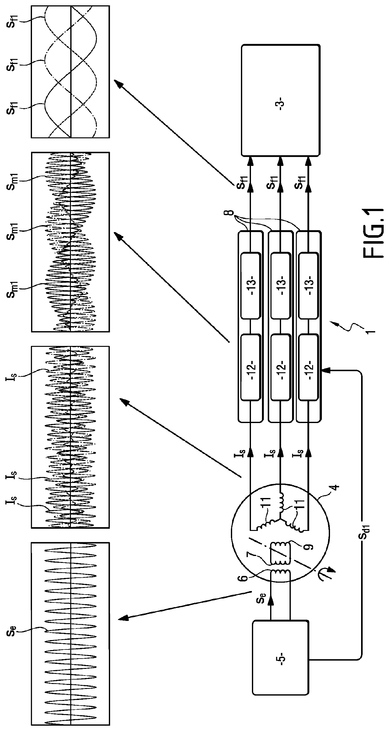
[0021]With reference to FIG. 1, the control device 1 of the invention is used in this example to control a three-phase synchronous electric motor.

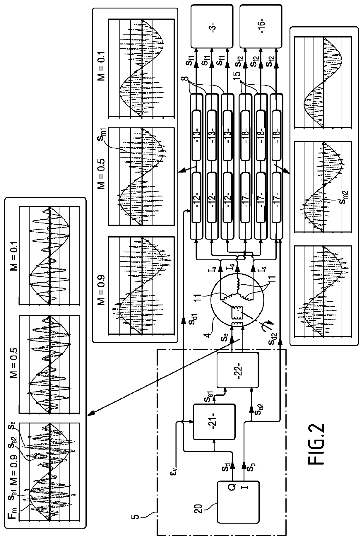
[0022]The control device 1 comprises a control module 3, specifically of the pulse width modulation (PWM) type, a synchro-transmitter 4, an excitation module 5, and three first synchronous demodulators 8.

[0023]The control module 3 is used for generating three-phase control signals to control an inverter that powers the electric motor.

[0024]The synchro-transmitter 4 comprises a first coupling winding 6, a second coupling winding 7, an excitation winding 9 constrained to rotate with a rotor of the electric motor, and three measurement windings 11.

[0025]The stationary first coupling winding 6 is connected to the excitation module 5. The first coupling winding 6 is magnetically coupled to the second coupling winding 7 which is itself constrained to rotate with the rotor of the electric motor. The terminals of the second coupling winding 7 are ...


PUM


Abstract

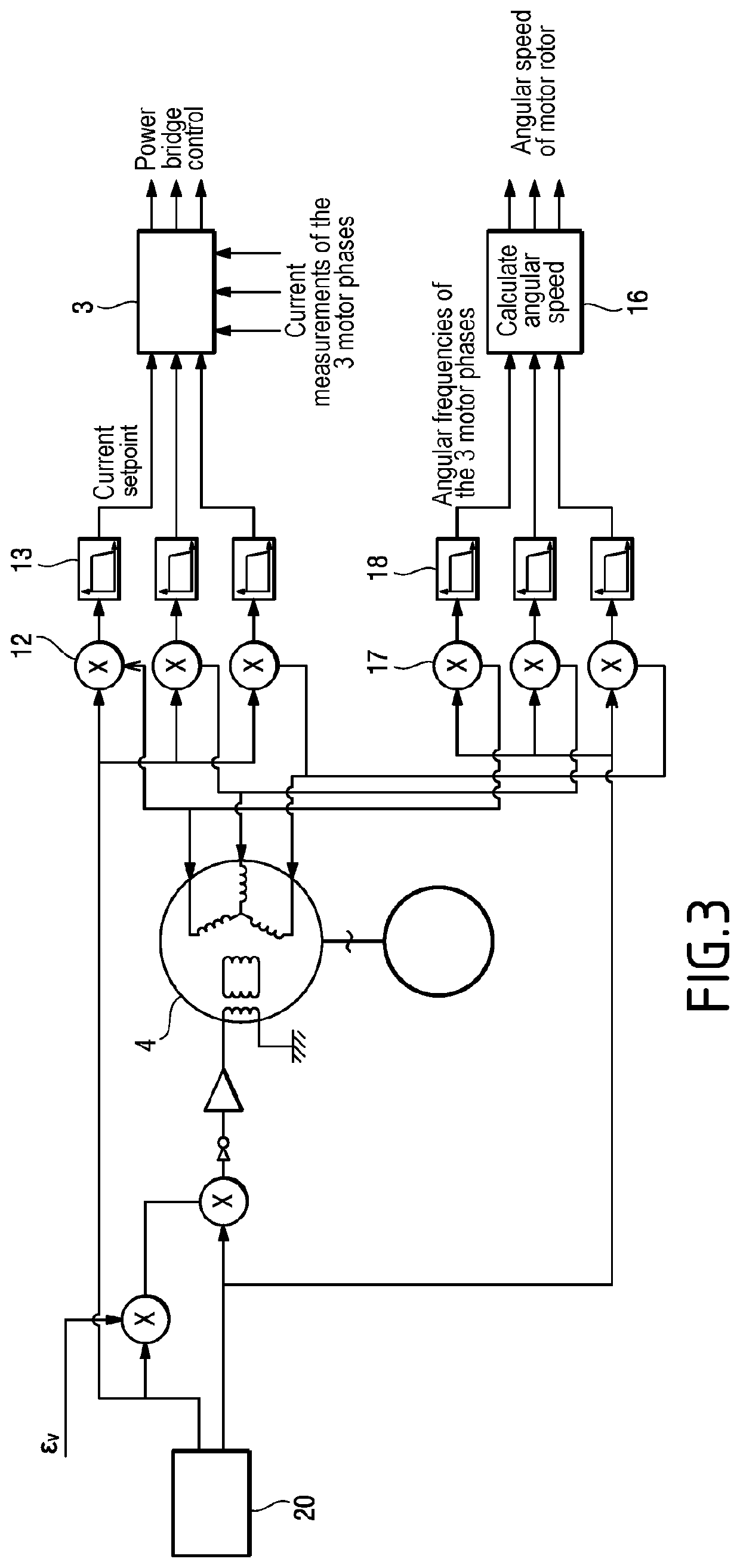
A control device for controlling an electric motor, the device comprising an inverter and a control module implementing a current servo-control loop for the electric motor; an excitation module producing an excitation signal; a synchro-transmitter comprising two coupling windings, an excitation winding constrained to rotate with a rotor of the electric motor, and three measurement windings, the excitation signal being applied to the excitation winding via the two coupling windings; three first synchronous demodulators, each connected to a respective one of the three measurement windings of the synchro-transmitter and to the excitation signal I, and each generating a current setpoint for the current servo-control loop for use by the control module; and three other synchronous demodulators, each connected to a respective one of the three measurement windings of the synchro-transmitter and to the excitation signal Q, and generating a signal providing information about the angular speed of the rotor of the motor for use by the control module.

Description

[0001]The invention relates to the field of electric motor control devices.BACKGROUND OF THE INVENTION[0002]Powering an electric motor such as a three-phase synchronous motor needs a direct current (DC) voltage to be converted into a controlled three-phase alternating current (AC) voltage in order to produce a current setpoint for the electric motor.[0003]For this purpose, it is known in the field of aviation to make use of digital solutions using components of the digital signal processor (DSP), application specific integrated circuit (ASIC), or field programmable gate array (FPGA) type. Those solutions are very complicated to design, to qualify, and to certify, in particular because of the high level of the requirements in the Radio Technical Commission for Aeronautics (RTCA) standards DO-254 and DO-278, or else they are not very reliable, or present insufficient performance in the face of electromagnetic disturbances generated by onboard networks, or in terms of the performance o...

Claims


Application Information

Patent Timeline
Patent Type & Authority Patents(United States)
IPC IPC(8): G05B11/01H02K24/00
CPCG05B11/015H02K24/00H02P6/08
Inventor GUILLOT, FRANÇOISPIATON, JERÔME
Owner SAFRAN ELECTRONICS & DEFENSE
Learn More