Display with observer tracking

a technology of observer tracking and display, applied in the field of display, can solve the problems of restricted aperture, complex array production, and inability to increase the number arbitrarily, and achieve the effect of reducing intensity fluctuations and influencing deflection effectiveness

Active Publication Date: 2016-12-27
SEEREAL TECHNOLOGIES
View PDF20 Cites 0 Cited by
  • Summary
  • Abstract
  • Description
  • Claims
  • Application Information

AI Technical Summary

Benefits of technology

[0022]In this case, the columns can be driven such that the tracking angle varies over the area of the cylindrical lens array, in order to obtain a field lens function and / or to achieve an adaptation of the width of the observer region assigned to the respective eye to the observer distance, in order that from all positions of the movement region a 3-D view can be perceived as far as possible without any disturbances.
[0039]By changing the voltage at a controllable polarization grating, it is possible to influence the deflection effectiveness and thus that proportion of the light which is deflected in the +1st or −1st order of diffraction depending on the circular polarization direction. Besides control of the intensity of the light sources and / or the modulation intensity of the light modulator, it is thus possible to reduce intensity fluctuations, for example, such as can occur for example as a result of different diffraction effectivenesses for individual polarization gratings of the polarization grating stack or for different spectral distributions of the light sources of the illumination device or further angle-dependent optical losses of the optical system.

Problems solved by technology

This number cannot be increased arbitrarily, since the primary and / or secondary light sources have technically dictated minimum dimensions.
However, such arrays are complicated to produce and have a restricted aperture on account of the cell height.
Mechanical deflection means such as deflection mirrors or rotatable prisms, which were likewise proposed, are sluggish and require a large structural volume.

Method used


Image

  • Display with observer tracking
  • Display with observer tracking
  • Display with observer tracking

Examples


Embodiment Construction

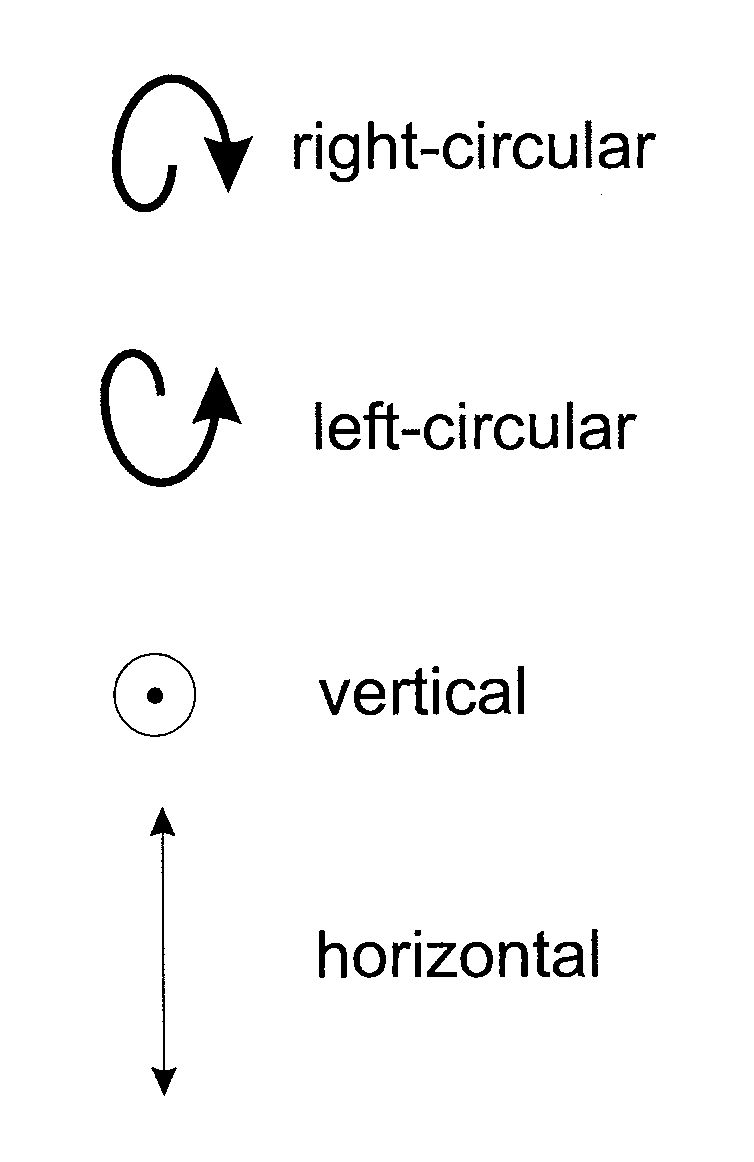
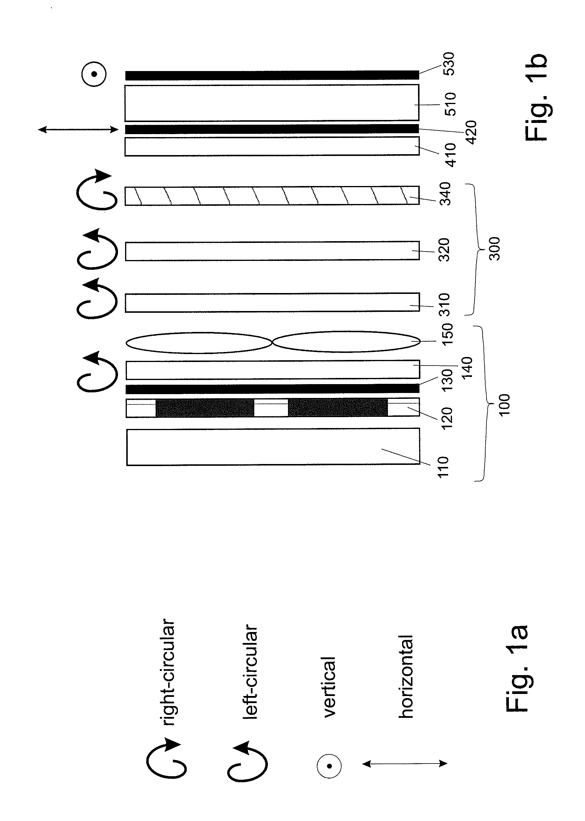
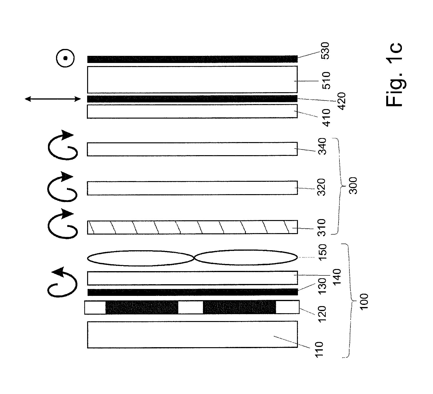
[0057]FIG. 1a shows the symbols—used in FIGS. 1 to 6—of the polarization direction leaving the respective illustrated optical element for the light passing through. The symbols are situated above the relevant optical elements in the drawings. Right and left circular polarization and vertical and horizontal linear polarization are illustrated.

[0058]A first configuration variant of the invention is illustrated purely schematically in FIGS. 1b to 1e. An illumination unit 100 that is collimated to the greatest possible extent and is controllable in the emission direction contains a light source matrix 110, a controllable slit diaphragm array 120, which can be embodied as a controllable liquid crystal matrix, a linear polarization filter 130, which can advantageously be configured as an output polarizer of the liquid crystal matrix, a birefringent retardation layer 140, for generating the required circular polarization from the linear polarization, which can advantageously be configured ...


PUM

PropertyMeasurementUnit
movementsaaaaaaaaaa
birefringent retardationaaaaaaaaaa
grating periodaaaaaaaaaa

Abstract

The invention relates to a display, in particular an autostereoscopic or holographic display, for representing preferably three-dimensional information, wherein the stereo views or the reconstructions of the holographically encoded objects can be tracked to the movements of the associated eyes of one or more observers in a finely stepped manner within a plurality of zones of the movement region. In this case, the zones are selected by the activation of switchable polarization gratings.

Description

CROSS REFERENCE TO RELATED APPLICATIONS[0001]This application claims the priority of PCT / EP2013 / 051423, filed on Jan. 25, 2013, which claims priority to German Application No. 10 2012 201166.8, filed Jan. 26, 2012, and German Application No. 10 2012 05479.7, filed Jun. 22, 2012, the entire contents of each of which are incorporated fully herein by reference.BACKGROUND OF THE INVENTION[0002]The invention relates to a display, in particular an autostereoscopic or holographic display, for representing preferably three-dimensional information, wherein the stereo views or the reconstructions of the holographically encoded objects can be tracked to the movements of the associated eyes of one or more observers.[0003]Displays for displaying three-dimensional information are known in a multiplicity of embodiments. Besides embodiments which require additional aids such as shutter or polarization spectacles for viewing the spatial scene, autostereoscopic displays do not require such aids. With...

Claims


Application Information

Patent Timeline
Patent Type & Authority Patents(United States)
IPC IPC(8): G09G5/00G02B5/20G03H1/22G02B5/32G02F1/29G02F1/1337G06F3/01G02F1/13G02B27/22H04N13/04G02B27/00G02B27/26G02F1/13363G03H1/02G02B30/25G02B30/31
CPCG06F3/013G02B5/201G02B5/32G02B27/0093G02B27/225G02B27/26G02F1/133753G02F1/292G03H1/2286G03H1/2294H04N13/0418H04N13/0468G02F1/1323G02F2001/133631G02F2001/133638G02F2001/133757G02F2001/291G02F2201/305G02F2203/07G02F2203/24G03H2001/0216G03H2001/221G03H2001/2236G03H2001/2242G03H2001/2292G03H2222/34G03H2222/36G03H2223/19G03H2223/20G03H2223/22G03H2223/23G03H2226/05G02B26/0808G02B27/286G02B27/4272G03H1/22G02B30/31H04N13/315H04N13/32H04N13/366H04N13/368H04N13/383H04N13/398G02F1/0136G02B30/25G02F1/133631G02F1/133757G02F1/133638G02F1/291H04N13/39G03H1/12G03H2001/0224
Inventor LEISTER, NORBERT
Owner SEEREAL TECHNOLOGIES
Why Eureka
Try Eureka