Machine and method for machining ends of crankshafts

a crankshaft and end-end technology, applied in the field of machine tools, can solve the problems of difficult to perform the loading and unloading in the two workstations from one and the same, and the machine cannot allow the machining of both ends of the cranksha

Active Publication Date: 2017-01-10
ETXE TAR SA
View PDF7 Cites 2 Cited by
  • Summary
  • Abstract
  • Description
  • Claims
  • Application Information

AI Technical Summary

Benefits of technology

[0011]According to the invention, said at least four fixing positions are arranged in two columns of fixing positions, each of which comprises at least two of the fixing positions located at a different height, for placing the crankshafts to be machined in two columns, each of which comprises at least two crankshafts arranged at a different height. Thus, each machining module can first machine an end of each crankshaft in a first one of said columns and then an end of each crankshaft of the other column.
[0012]Furthermore, according to the invention, said support structure is rotatably arranged, such that it can perform a rotation of at least 180 degrees.
[0013]Several effects can thus be achieved.
[0014]One effect is that in the event that one of said machining modules stops working, the other one can machine both ends of each crankshaft, first machining one end and then, after a rotation of 180 degrees of the support structure, also machining the other end of the crankshaft.
[0015]Another advantage is that by means of rotations of less than 180 degrees, for example, of 20-70 degrees (for example, of 30, 45 or 60 degrees) or of (approximately) 90 degrees, machining operations which were not possible, or which would have been difficult, can be performed in the initial position. This increases the possibilities of performing special or complex machining operations without needing to have additional machining heads and / or without performing tool-head changes.
[0016]Another advantage, compared with a machine such as the one described in WO-A-2009 / 103825, is that all the crankshafts can be loaded in, and unloaded from, the support structure in a single loading and unloading station by means of a rotation of 180 degrees of the support structure, by means of which both of the two columns of crankshafts can be selectively placed in the loading and unloading station or position. This can be advantageous in many cases.

Problems solved by technology

Nevertheless, and despite the fact that the machine and method described in WO-A-2009 / 103825 can work satisfactorily from many points of view, they can have several limitations.
For example, it may be difficult to perform the loading and unloading in the two workstations from one and the same loading and unloading point or station.
Another possible limitation is that in the event of a breakdown in one of the machining modules, the machine does not allow machining both ends of the crankshafts.
Another possible limitation is that it may be difficult to perform certain machining operations, which require a determined working angle between the tool-head and the crankshaft (for example, the machining of the keyway or of lightening holes), without using additional machining modules or tool-head changes.

Method used


Image

  • Machine and method for machining ends of crankshafts
  • Machine and method for machining ends of crankshafts
  • Machine and method for machining ends of crankshafts

Examples


Embodiment Construction

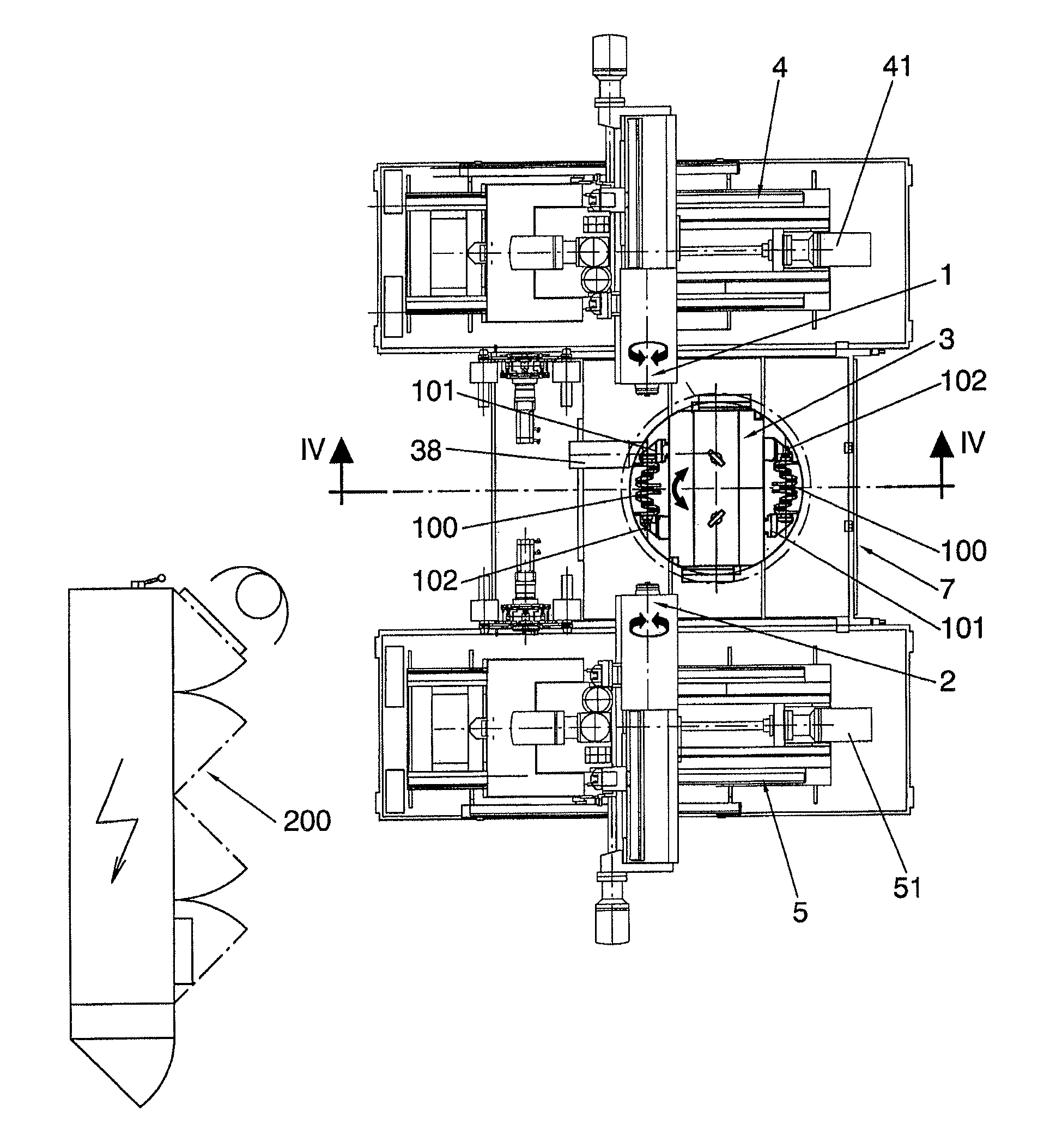
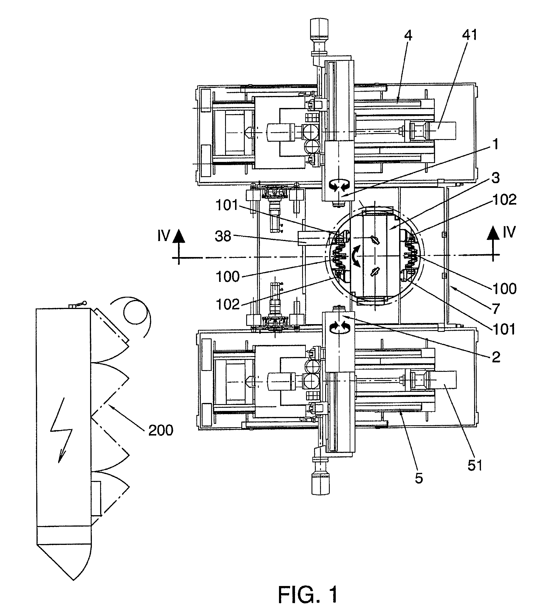
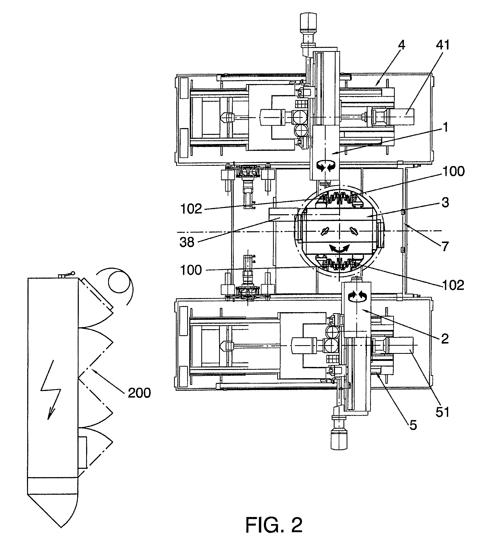
[0007]A first aspect of the invention relates to a machine for machining ends of crankshafts, comprising:

[0008]a first machining module configured to simultaneously machine at least two crankshafts (i.e., the first module can comprise, for example, two spindles or a multi-spindle head with respective tools for simultaneously machining two or more crankshafts or, more specifically, an end of each of said crankshafts);

[0009]a second machining module configured to simultaneously machine at least two crankshafts (i.e., the second module can also comprise, for example, two spindles or a multi-spindle head with respective tools for simultaneously machining two or more crankshafts or, more specifically, an end of each of said crankshafts; the first and the second machining module can be identical and arranged facing one another); and

[0010]a support structure for supporting crankshafts, said support structure comprising at least four crankshaft fixing positions for the machining of such cra...


PUM

PropertyMeasurementUnit
angleaaaaaaaaaa
angleaaaaaaaaaa
angleaaaaaaaaaa

Abstract

The invention relates to a machine comprising a first machining module (1) configured to simultaneously machine at least two crankshafts, a second machining module (2) configured to simultaneously machine at least two crankshafts, and a support structure (3) with at least four crankshaft fixing positions (31, 32, 33, 34) for the machining of such crankshafts. The support structure (3) is located between the machining modules. The fixing positions (31, 32, 33, 34) are arranged in two columns (35, 36) of fixing positions, each of which comprises at least two of the fixing positions (31, 32; 33, 34) located at a different height, and the support structure (3) is rotatably arranged, such that it can perform a rotation of at least 180 degrees.

Description

TECHNICAL FIELD OF THE INVENTION[0001]The invention is comprised in the technical field of machine tools and, more specifically, it relates to a machine for machining crankshafts, for example, crankshafts for automotive vehicles.BACKGROUND OF THE INVENTION[0002]The ends of crankshafts for automotive vehicles, for example, for passenger cars, are usually machined in machines specifically designed for performing the corresponding operations. For example, the crankshafts can be arranged in a workstation located between two machining modules (each can be configured to simultaneously machine a plurality of crankshafts, generally using a tool for each crankshaft, for example, using a multi-spindle head), such that a first machining module machines one end of the crankshaft (or one end of several crankshafts) and the other machining module simultaneously machines the other end of the crankshaft (or of the crankshafts).[0003]To achieve a high production rate and an efficient use of the mach...

Claims


Application Information

Patent Timeline
Patent Type & Authority Patents(United States)
IPC IPC(8): B23Q39/02B23Q39/04B23C3/06B23Q39/00
CPCB23C3/06B23Q39/026B23Q39/04B23Q2039/002B23Q2230/006Y10T409/30392Y10T409/30756Y10T409/303752Y10T409/307168Y10T409/309016Y10T483/1795Y10T483/1891
Inventor GARCES, JORGE IBARRAARISTIZABAL, IBON IRIBARREN
Owner ETXE TAR SA
Why Eureka
Try Eureka