A dual-stage thermoelectric material device
A technology of thermoelectric materials and thermoelectric elements, which is applied in the directions of thermoelectric device node lead-out materials, measurement devices, thermoelectric device parts, etc., can solve the problems such as the inability to effectively utilize the figure of merit of thermoelectric materials and the low conversion efficiency of thermoelectric power generation devices, etc. To achieve the effect of improving power generation efficiency and improving safety
- Summary
- Abstract
- Description
- Claims
- Application Information
AI Technical Summary
Problems solved by technology
Method used
Image
Examples
Embodiment 1
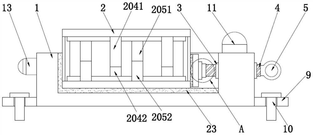
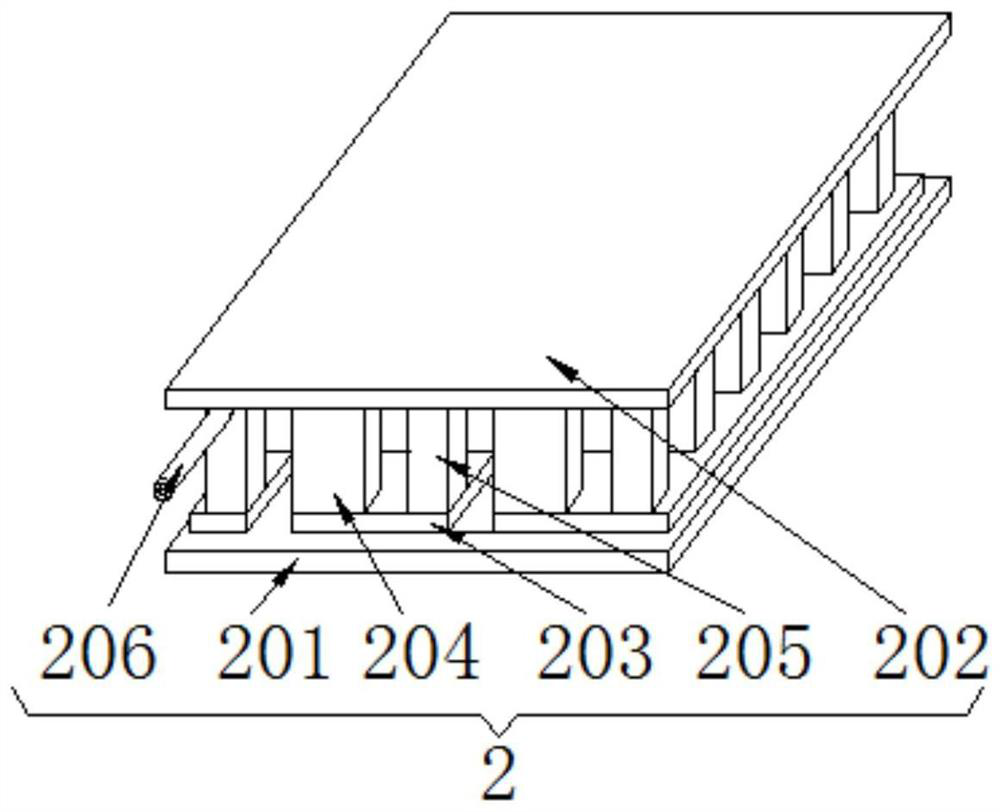
[0037] Embodiment 1 is the basic structure of a kind of embodiment, as figure 1 and figure 2As shown, it includes a base 1 and a thermoelectric device body 2, a groove is opened on the upper surface of the base 1, and a thermoelectric device body 2 is arranged inside the groove, and the thermoelectric device body 2 includes a lower substrate 201 and an upper substrate 202. , conductive plate 203, double-stage P-type thermoelectric element 204, double-stage N-type thermoelectric element 205 and electrode rod 206, the lower substrate 201 and the upper substrate 202 are symmetrically arranged, the lower surface of the lower substrate 201 and the groove The inner side wall is attached, and the opposite side of the lower substrate 201 and the upper substrate 202 are fixedly connected with a conductive plate 203, and the two-stage P-type thermoelectric element 204 and the double-stage N-type thermoelectric element are arranged alternately between the two conductive plates 203. ele...
Embodiment 2
[0046] Embodiment 2 is a technical solution further optimized on the basis of Embodiment 1. On the basis of Embodiment 1, Embodiment 2 further adds a fixing device arranged between the base 1 and the thermoelectric device body 2 .
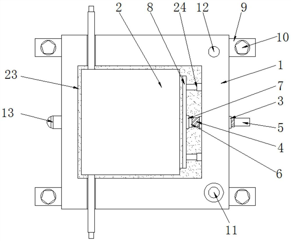
[0047] Such as figure 1 , image 3 and Figure 7 As shown, the fixing device includes a threaded cap 3 clamped on the side of the base 1, and the threaded cap 3 is internally threaded with a threaded column 4, and the threaded column 4 passes through one end of the base 1 and is fixed to the rotating handle 5;
[0048] The left end of the threaded column 4 is fixedly connected to the right end of the rotating shaft 6, the outer surface of the rotating shaft 6 is sleeved with a bearing 7, and the bearing 7 is clamped on the right side of the extruding plate 8, and the extruding plate 8 The left side of the base 1 is attached to the right side of the thermoelectric device body 2, and two mounting plates 9 are respectively fixed under the left and r...
Embodiment 3
[0056] Embodiment 3 is a technical solution further optimized on the basis of Embodiment 1 or Embodiment 2, and Embodiment 3 further adds a temperature control device arranged on the base on the basis of Embodiment 1 or Embodiment 2.
[0057] Such as Figure 4 and Figure 5 As shown, the temperature control device includes an alarm horn 11 and an alarm lamp 12 fixedly installed on the upper surface of the base 1, a temperature sensor 13 is fixedly installed on the left side of the base 1, and a control box 14 is arranged on the front. The front of box 14 is fixedly installed with display screen 15 and control button, and described control box 14 is provided with single-chip microcomputer 17 and battery slot;
[0058]The single-chip microcomputer 17 is provided with a signal conversion module 18, a storage module 19, a comparison module 20 and an alarm module 21, the input of the signal conversion module 18 and the output signal of the temperature sensor 13, the output of the ...
PUM
 Abstract
Description
Claims
Application Information
 - R&D
- Intellectual Property
- Life Sciences
- Materials
- Tech Scout
- Unparalleled Data Quality
- Higher Quality Content
- 60% Fewer Hallucinations
Browse by: Latest US Patents, China's latest patents, Technical Efficacy Thesaurus, Application Domain, Technology Topic, Popular Technical Reports.
© 2025 PatSnap. All rights reserved.Legal|Privacy policy|Modern Slavery Act Transparency Statement|Sitemap|About US| Contact US: help@patsnap.com


