Electromagnetic contactor

a contactor and electromagnetic technology, applied in the field of electromagnetic contactors, can solve problems such as abrasion and damage, and achieve the effect of reducing the transformation and damage of the lever

Inactive Publication Date: 2017-01-10
LSIS CO LTD
View PDF25 Cites 0 Cited by
  • Summary
  • Abstract
  • Description
  • Claims
  • Application Information

AI Technical Summary

Benefits of technology

[0016]Therefore, an aspect of the detailed description is to provide an electromagnetic contactor capable of reducing transformation and damage of a lever of a ‘b’ contact switch of a movable core assembly.
[0024]The electromagnetic contactor according to an embodiment of the present invention can have the following advantages.
[0025]Firstly, since the button for operating the ‘b’ contact switch is formed as an elastic member, an impact generated when a force is applied to the switch lever is attenuated. This can increase durability and reduce damage, thereby enhancing reliability of an operation of the ‘b’ contact switch.

Problems solved by technology

However, in the conventional electromagnetic contactor, abrasion and damage occur due to repeated collisions between the switch manipulation protrusion 145 and the switch lever 128.

Method used


Image

  • Electromagnetic contactor
  • Electromagnetic contactor
  • Electromagnetic contactor

Examples


Embodiment Construction

[0038]Description will now be given in detail of preferred configurations of an electromagnetic contactor according to the present invention, with reference to the accompanying drawings.

[0039]FIG. 5 is an exploded perspective view of an electromagnetic contactor according to an embodiment of the present invention. FIG. 6 is a perspective view of a movable core assembly according to an embodiment of the present invention. FIG. 7 is a perspective view illustrating a state where a movable core of FIG. 5 has been assembled into a bobbin. Various embodiments of the present invention will be explained in more detail with reference to the attached drawings.

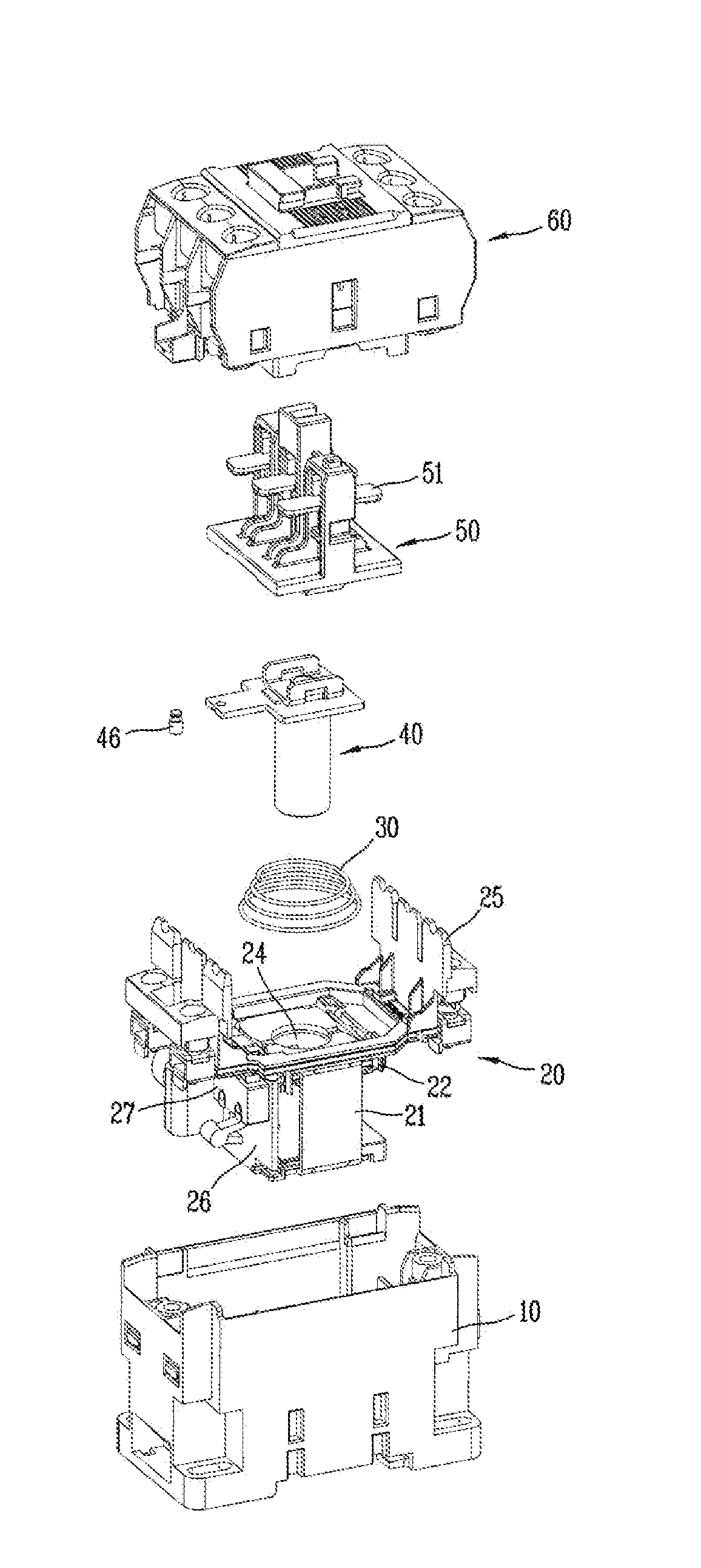
[0040]The electromagnetic contactor according to an embodiment of the present invention includes a lower frame 10 having an accommodation space therein; a bobbin 20 having a fixed core 21, and accommodated in the lower frame 10; a movable core 40 inserted into the bobbin 20 so as to be moveable up and down; a spring 30 installed between ...


PUM


Abstract

An electromagnetic contactor includes: a lower frame having an accommodation space therein; a bobbin having a fixed core, and accommodated in the lower frame; a movable core inserted into the bobbin so as to be moveable up and down; a spring installed between the bobbin and the movable core, and configured to provide an upward restoration force to the movable core; and a ‘b’ contact switch installed at one side of the bobbin, wherein a button for operating a switch lever of the ‘b’ contact switch is provided at a movable core plate positioned above the movable core.

Description

CROSS-REFERENCE TO RELATED APPLICATION[0001]Pursuant to 35 U.S.C. §119(a), this application claims the benefit of earlier filing date and right of priority to Korean Application No. 10-2014-0106011, filed on Aug. 14, 2014, the contents of which is incorporated by reference herein in its entirety.BACKGROUND OF THE INVENTION[0002]1. Field of the Invention[0003]The present invention relates to an electromagnetic contactor, and more particularly, to an electromagnetic contactor including a ‘b’ contact switch at a coil circuit portion.[0004]2. Background of the Invention[0005]Generally, a direct current relay or an electromagnetic contactor is a type of electrical circuit switching device for performing a mechanical driving and transmitting a current signal using an electromagnet. The direct current relay or electromagnetic contactor is installed at various types of industrial equipment, machines, vehicles, etc.[0006]The electromagnetic contactor may include a main contact mechanism for ...

Claims


Application Information

Patent Timeline
Patent Type & Authority Patents(United States)
IPC IPC(8): H01H3/00H01H50/56H01H50/18H01H47/10H01H50/20H01H50/54
CPCH01H50/56H01H47/10H01H50/18H01H50/20H01H50/546H01H50/645H01H50/02H01H50/36H01H50/38
Inventor JANG, HYUN IL
Owner LSIS CO LTD
Why Eureka
Try Eureka