Multifunctional Switched Reluctance Generator High Voltage DC System

A reluctance generator and multi-function switch technology, applied in the direction of controlling the generator through the change of the magnetic field, controlling the generator, generator control circuit, etc., can solve the problems of no double-fed capability, weak fault ride-through capability, low reliability, etc. , to achieve the effect of improving the ability of low voltage ride through, broadening the adaptability and application range, enhancing safety and reliability

Active Publication Date: 2022-02-11
CHINA JILIANG UNIV
View PDF5 Cites 0 Cited by
  • Summary
  • Abstract
  • Description
  • Claims
  • Application Information

AI Technical Summary

Problems solved by technology

[0003] At present, high-voltage direct current transmission is one of the key transmission methods in my country. DC microgrid is also a model that is developed under the framework of smart grid in many areas. DC microgrid is often combined with small and medium-sized wind power, small hydropower and other new energy generators. , and most of the current generator sets are AC generators, the AC power sent out must be rectified first, and then boosted. There are many levels of power conversion, complex conversion, high loss and low efficiency, and high cost. The development of DC transmission and DC microgrid field and smart grid
[0004] In some areas of independent power generation systems, such as remote areas and islands in the wild, where the power grid cannot be covered, independent diesel generator sets, or small wind power or wind-solar hybrid devices are often used to supply power. The generators are generally alternators, but these areas often require Equipped with a large number of storage battery installations, which must be converted to DC charging, there are similar problems
[0005] In the various small and medium-sized power generation systems mentioned above, especially those with unstable input power such as wind power, the existing generator sets are often permanent magnet synchronous generators or squirrel-cage asynchronous generators, especially squirrel-cage asynchronous generators. Feedback capability, the adaptability after grid connection is extremely poor, and the fault ride-through ability is very weak. Some use DC generators. Although they directly generate DC power, their structures are complicated, especially the existence of commutators also greatly increases the later maintenance. Workload, low reliability, has been gradually abandoned

Method used


Image

  • Multifunctional Switched Reluctance Generator High Voltage DC System

Examples


Embodiment Construction

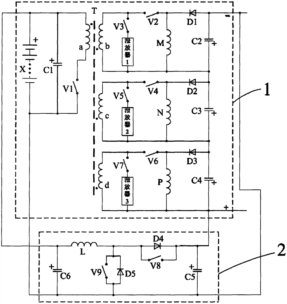
[0028] as attached figure 1 Shown is the main structure diagram of the multifunctional switched reluctance generator HVDC system of this embodiment. The switched reluctance generator of this embodiment is a three-phase winding, and the overlap coefficient is zero. This embodiment is only a typical example, such as Switched reluctance generators with two-phase windings or four-phase or more windings have the same converter main circuit mode and can be expanded, so they should also be within the protection scope of the present invention.

[0029] The multifunctional switched reluctance generator high-voltage direct current system is composed of a converter main circuit 1 and a converter auxiliary circuit 2, the two ends of the output of the converter main circuit 1 are connected with the input terminals of the converter auxiliary circuit 2, and the output of the converter auxiliary circuit 2 Both ends are connected to both ends of the input of the converter main circuit 1;

[003...


PUM


Abstract

The multifunctional switched reluctance generator high-voltage DC system is composed of a converter main circuit and a converter auxiliary circuit. The converter main circuit can be expanded to adapt to different phases of switched reluctance generators. It has an isolation link, and its output bus voltage is each The sum of the output voltages of the phase winding converters can directly obtain high-voltage direct current. The converter auxiliary circuit has the ability to transmit bidirectional power, which can absorb the bus power to charge the excitation power supply of the converter main circuit, that is, the battery pack, and can also feed back when necessary. The system has strong flexibility and high intelligence, greatly reduces intermediate links for DC loads or DC microgrids, and has high reliability. It is suitable for wind power, small hydropower, diesel generators, etc. facing DC microgrids or independent DC field of load generation.

Description

technical field [0001] The invention relates to the fields of a DC micro-grid power generation system, an independent power generation system, etc., in particular to a direct-current multifunctional high-voltage conversion system and a control method thereof under a switched reluctance generator. Background technique [0002] The structure of the switched reluctance motor is simple and strong. There is no winding or permanent magnet on the rotor. It is only made of laminated silicon steel sheets with concave and convex grooves. The heat dissipation pressure is small, the reliability is high, and the manufacturing cost is low. A certain phase winding in the stator does not work. It does not affect the normal operation of other phase windings, has strong fault tolerance and has broad application prospects. [0003] At present, high-voltage direct current transmission is one of the key transmission methods in my country. DC microgrid is also a model that is developed under the ...

Claims


Application Information

Patent Timeline
Patent Type & Authority Patents(China)
IPC IPC(8): H02P9/30H02P9/00
CPCH02P9/007H02P9/30H02P2101/15
Inventor 孙冠群
Owner CHINA JILIANG UNIV
Why Eureka
Try Eureka