Electrical connector having terminals embedded in a packaging body

a technology of electrical connectors and packaging bodies, applied in the direction of electrical devices, coupling device connections, printed circuits, etc., can solve the problems of terminal damage, slow assembly speed, degraded reliability of electronic connectors, etc., and achieve the effect of accelerating assembly speed and high reliability

Active Publication Date: 2017-01-10
CHIEF LAND ELECTRONICS CO LTD
View PDF8 Cites 25 Cited by
  • Summary
  • Abstract
  • Description
  • Claims
  • Application Information

AI Technical Summary

Benefits of technology

[0007]The instant disclosure provides an electrical connector, having terminals embedded in a packaging body to form a terminal wafer, and the terminal wafer is assembled in a housing, so as to provide a steady structure with high reliability, to prevent terminals from being deformed and accelerate the assembling speed.
[0009]Thus, the present disclosure has advantages as follows. The present disclosure provides a steady structure with a high reliability, and does not affect the transmitting performance at high frequency. The corresponding curve contour is a benefit to lower the electromagnetic interference between the first terminals and the second terminals, to enhance the efficiency of signal transmitting.

Problems solved by technology

However, the terminal is easily deformed because of resistance force during the assembly process, thus the reliability of the electronic connector is degraded.
Further, the assembly speed is slow and the terminals may be damaged.
Moreover, some terminals may be made of precious metal for strengthening the rigidity to avoid deforming during the assembly process, and this way adds cost.

Method used


Image

  • Electrical connector having terminals embedded in a packaging body
  • Electrical connector having terminals embedded in a packaging body
  • Electrical connector having terminals embedded in a packaging body

Examples


Embodiment Construction

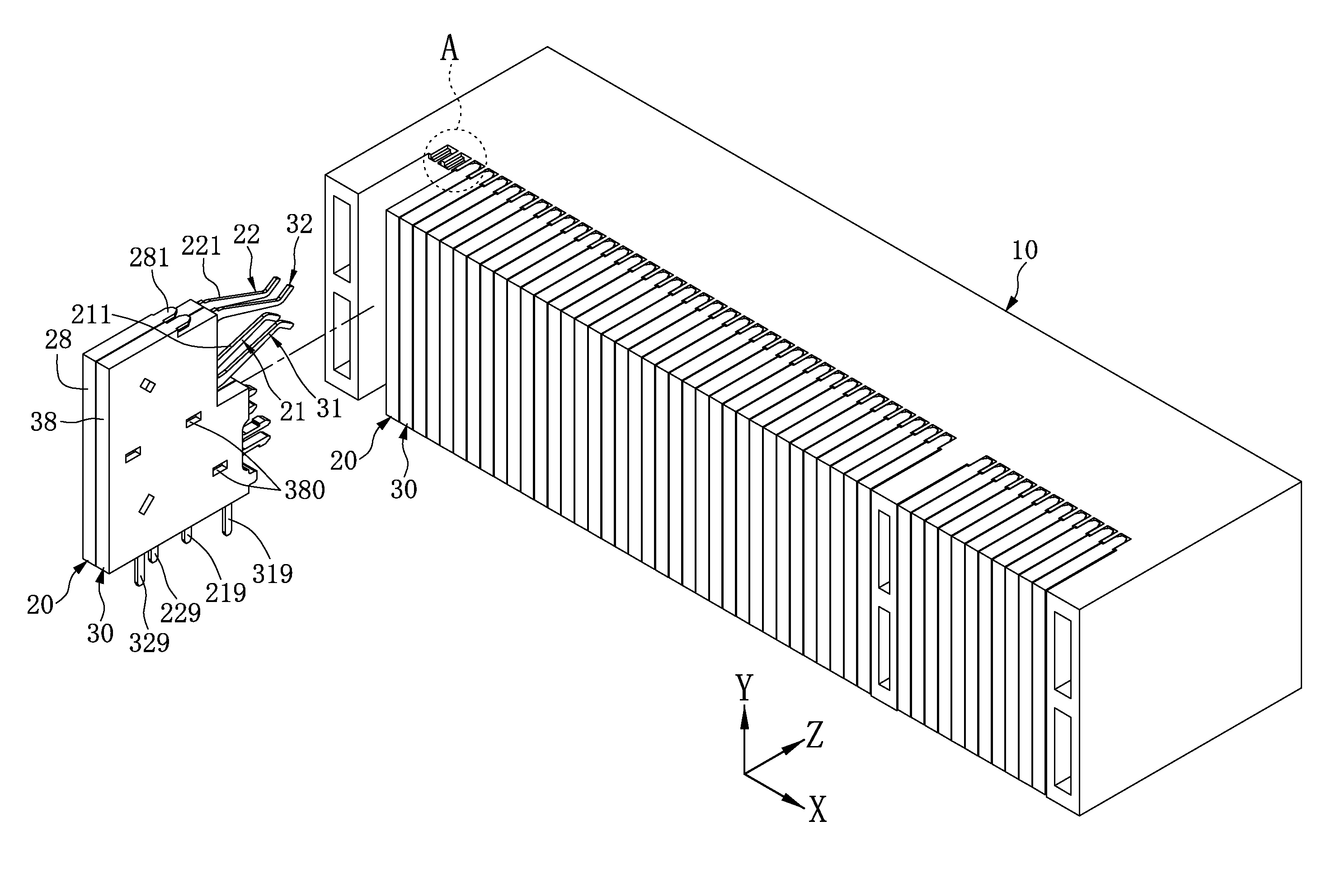
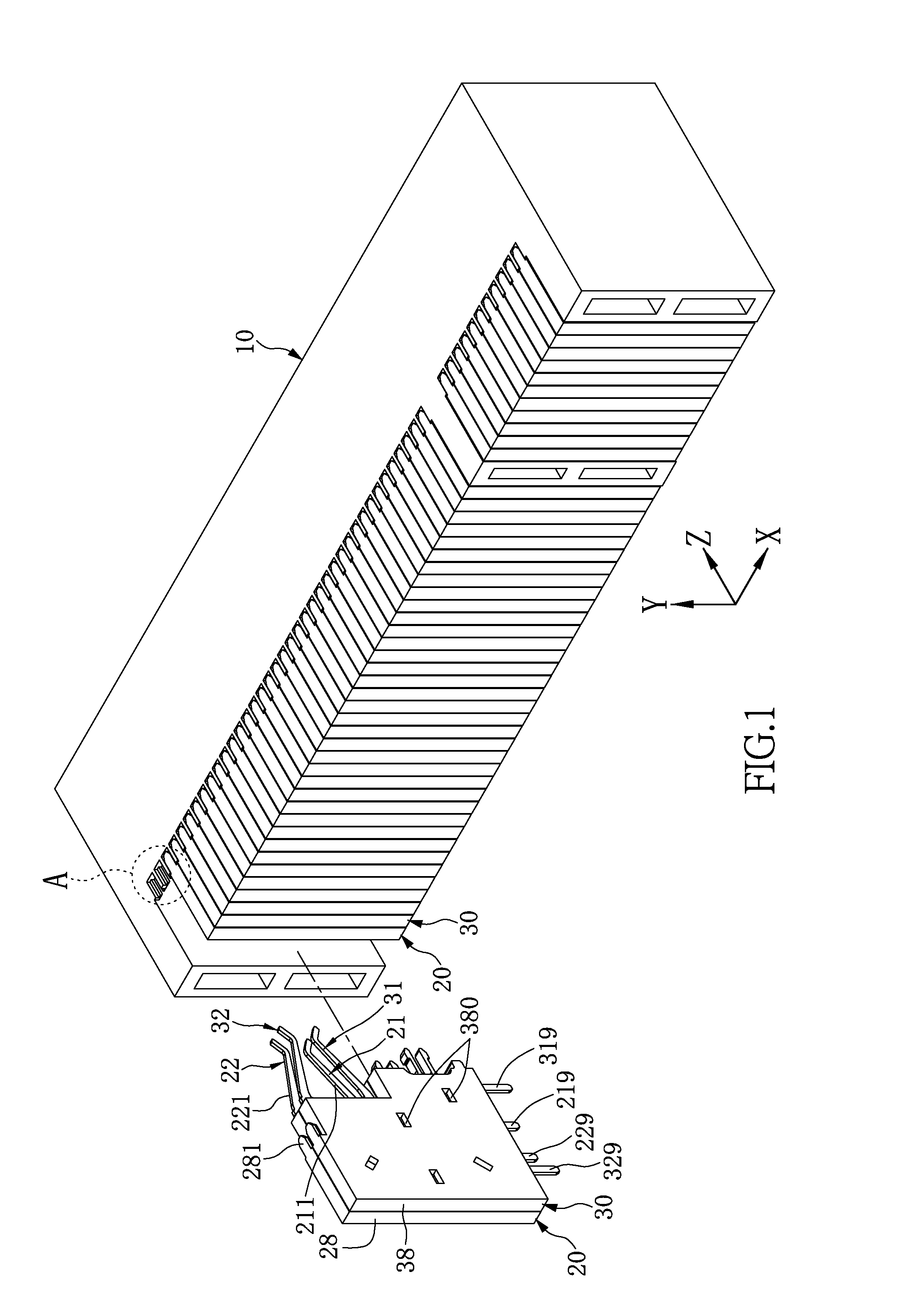
[0021]Please refer to FIG. 1 to FIG. 3. FIG. 1 and FIG. 2 are different perspective views of the electrical connector of the present disclosure; and FIG. 3 is a perspective view of a terminal-wafer set separated from a housing according to the present disclosure. The present disclosure provides an electrical connector, which includes a housing 10, and a plurality of terminal wafers 20, 30. The housing 10 is made of insulating material. Each two neighboring terminal wafers 20, 30 is configured as a terminal wafer assembly.

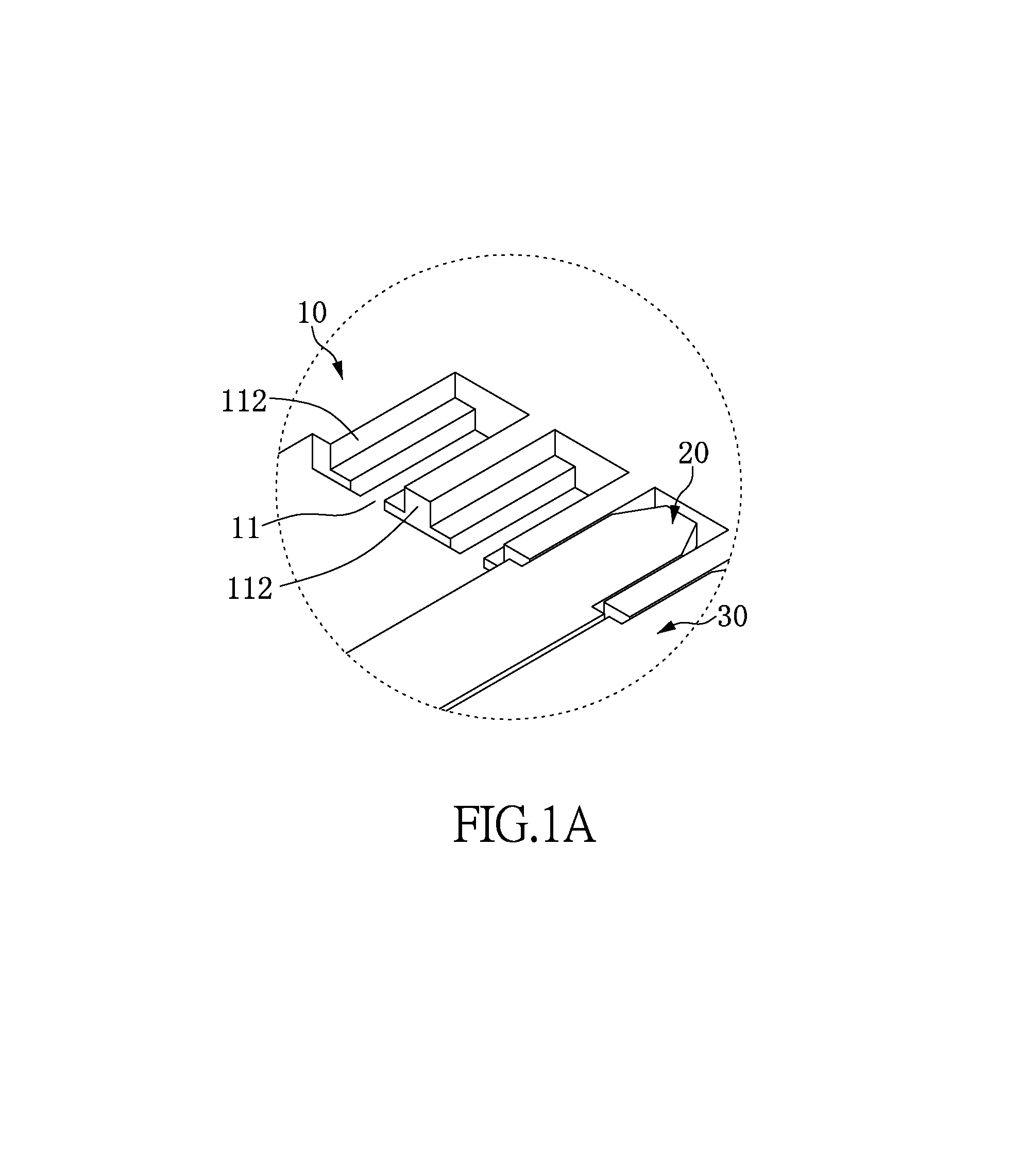
[0022]As shown in FIG. 3, the housing 10 is formed with a plurality of terminal slots 101, 102 in a traverse direction thereof, that is, in the X-axis direction of the figures. The terminal slots 101, 102 are arranged in an upper row and a lower row parallel to each other in the traverse direction.

[0023]As shown in FIG. 1 and FIG. 2, the terminal wafers 20, 30 are adjacent to each other in the traverse direction, and retained in the housing 10 along a plugging direc...


PUM


Abstract

An electrical connector includes a housing and a plurality of terminal wafers. The housing is formed with a plurality of terminal slots along a traverse direction. The terminal wafers are contiguous to each other and retained in the housing. Each terminal wafer has a first terminal, a second terminal and a packaging body. The first terminal has a first contacting section, a first soldering portion and a first embedded section. The second terminal has a second contacting section, a second soldering portion and a second embedded section. The first and second contacting sections are extended along a plugging direction into one corresponding terminal slot. The packaging body wraps the first and second embedded sections. A curve contour of the first embedded section is corresponded to a curve contour of the second embedded section, so that an attachment relationship is configured with substantial identical distance therebetween.

Description

BACKGROUND OF THE INVENTION[0001]1. Field of the Invention[0002]The instant disclosure relates to an electrical connector, in particular, to an electrical connector having a plurality of terminals formed in pairs and assembled side by side in an insulating housing for clamping and electrically connecting terminals of an electrical plug connector.[0003]2. Description of Related Art[0004]Electrical connectors have been widely used to transmit electricity or signals between two devices. There is one kind of electrical connector having a plurality of terminals formed in pairs and assembled side by side in an insulating housing for clamping and electrically connecting terminals of an electrical plug connector, such as Peripheral Component Interconnect Express (PCIe) connector.[0005]Such kind of assembly process usually needs to insert the terminals one by one in the terminal grooves of the insulating housing. The terminals usually are formed with many interference portions in a hook shap...

Claims


Application Information

Patent Timeline
Patent Type & Authority Patents(United States)
IPC IPC(8): H01R12/00H01R13/514H01R4/02H05K1/00
CPCH01R13/514H01R4/02H01R13/405H01R13/518H01R13/6467H01R13/6587
Inventor PAO, CHUNG-NANCHOU, CHIN-HSIANGCHEN, PO-SHENLIN, YU-HSIUNGCHEN, HSIAO-CHUNG
Owner CHIEF LAND ELECTRONICS CO LTD
Why Eureka
Try Eureka