Minimally invasive device for surgical operations

a minimally invasive, surgical technology, applied in the direction of surgical saws, internal osteosynthesis, internal osteosynthesis, etc., can solve the problems of difficult medical team use, small structure cutting, and surgical procedure being more difficult and dangerous, so as to facilitate the medical team's handling, save patient time, and reduce the effect of surgical procedur

Active Publication Date: 2017-01-17
RUSSI MARTIN
View PDF10 Cites 1 Cited by
  • Summary
  • Abstract
  • Description
  • Claims
  • Application Information

AI Technical Summary

Benefits of technology

[0020]Bearing in mind the shortcomings of the prior art, one of the objects of the present invention is to provide a device for use in surgical procedures which requires minimal invasion, and which may be used in osteotomy and / or tissue removal procedures in a convenient and simple way
[0021]An additional object of the present invention is to provide a device for use in surgical procedures which requires minimal invasion and which reduces to a minimum the time required to carry out the surgical procedure and the internal damage caused to the patient.
[0022]An additional object of the present invention is to provide a minimally invasive device for use in surgical procedures which enables carrying out surgical procedures which are safer and less invasive for the patient.

Problems solved by technology

In addition to the risk of damaging organs or surrounding tissue in the area where the incisions are carried out, there is also the risk of cutting a blood vessel which could render the surgical procedure more difficult and dangerous.
However, the above device described above has a drawback in that its design is not ergonomic, which makes its use by the medical team more difficult.
Another disadvantage is that the cut carried out by the device is performed by material removal instead of a clean cut, as well as the further drawback that being a very flexible device, only very small structures may be cut.
In addition to the above, said device does not include a mechanism which enables regulation and measurement of the cut in the spatial planes.
One of the main disadvantages of said device is that it is conceived solely to locate a cord or sling on a tissue or structure that so requires, not for cutting bone structures.
In addition to the above, to position the cord or sling requires removal of both positioning elements and of the guiding piece, which makes operating the device considerably difficult.

Method used


Image

  • Minimally invasive device for surgical operations
  • Minimally invasive device for surgical operations
  • Minimally invasive device for surgical operations

Examples


first embodiment

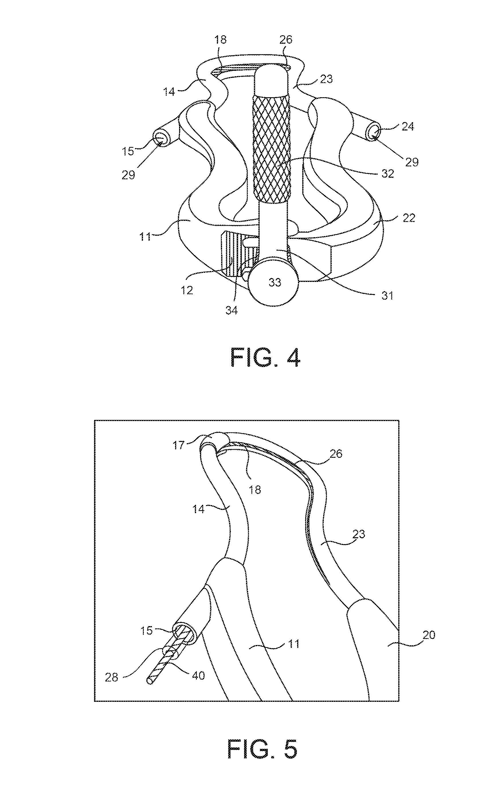
[0072]Regarding FIGS. 10 and 11, they show a second additional embodiment of spatial positioning element 60, where said element 60, in addition to including a straight arm 61, a curved arm 66 and an intermediate arm 610 as described in said element 60, includes a vertical stem 85, the lower end of which includes a sphere 86, which, as will be described below, is inserted in a spherical cavity 94 located in device 100, allowing rotational movement of spatial positioning element 60 with respect to said device 100; while the upper end of said vertical stem 85 is inserted in the first central channel 611 of intermediate arm 610, in such a way that both straight arm 61 and intermediate arm 610 are connected by said vertical stem 85.

second embodiment

[0073]In order that this second additional embodiment of spatial positioning device 60 may be connected to device 100, primary main body 10 or secondary main body 20, and particularly primary holding handle 11 or secondary holding handle 21 include anchoring mechanism 80, which includes a retaining indentation 93 in the shape of a wine glass, which has a spherical cavity 94 on its upper end to retain sphere 86 of vertical stem 85 in such a way as to form a ball joint, and on its lower end, which has a tubular shape and is threaded, said retaining indentation 93 includes a threaded holding key 95 in the shape of a “Y”, the vertical end of said “Y” being inserted in the lower end of retaining indentation 93. Threaded key 93, when rotated in one direction, firmly grasps sphere 86, when turned in the opposite direction the force with which sphere 86 is held is diminished, thus allowing angular movement of device 100 over spatial positioning element 60 on the sagittal plane.

[0074]It is i...

third embodiment

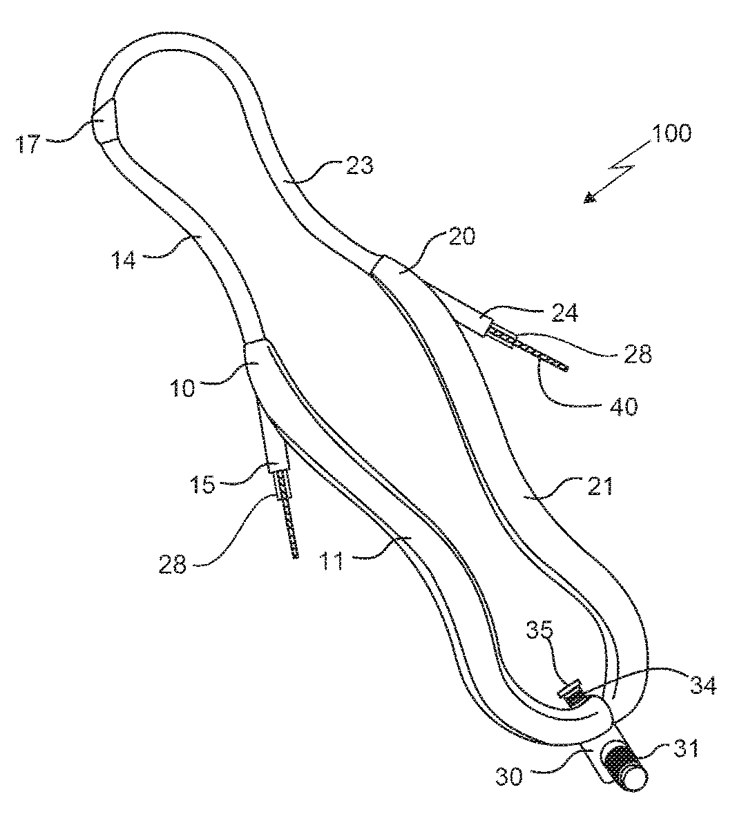
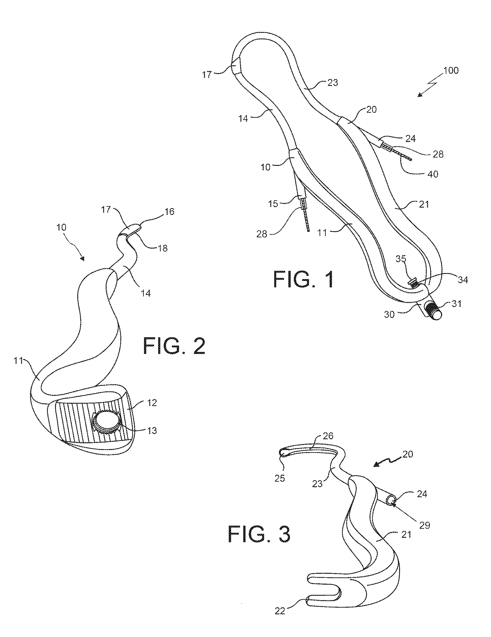
[0097]Now, referencing FIG. 21, it shows the minimally invasive device for surgical procedures 300, which is formed by at least a couple of assembly elements formed by a primary main body 310 and a secondary main body 320 joined at their proximal end, a coupling element 330 which joins both primary and secondary main bodies 310 and 320 joined at their proximal end; a coupling element 330 which joins both primary and secondary main bodies 310 and 320 respectively at their intermediate section and at their distal end, a threading element (such as the threading element 28 shown in FIGS. 1 and 5) which is placed internally starting from the intermediate section of device 300, continues to its proximal end and returns to said intermediate section, and a multifunction element 340 which is located inside the threading element.

[0098]Primary main body 310 is formed by a primary holding handle 311 which projects upwards from its distal end to approximately two third parts of the total length ...


PUM


Abstract

The present invention is related to a minimally invasive device for surgical procedures which generally comprises at least a pair of assembly elements formed by a primary main body and a secondary main body joined together at their proximal and distal ends; a fastening element which is inserted in the distal end of both primary and secondary main bodies respectively, which is employed to keep them joined together; a threading element which is inserted in its inner section from the intermediate section of said device, continues to its proximal end and returns to its intermediate section on the opposite end; and a multifunction element located on the inside of the threading element.

Description

STATEMENT OF RELATED APPLICATIONS[0001]This application is a 35 U.S.C. §371 national phase filing of International Application No. PCT / IB2012 / 057579 filed on Dec. 21, 2012, and further claims priority to Uruguayan Patent Application No. 33.839 filed on Dec. 22, 2011, with the disclosures of the foregoing applications hereby being incorporated by reference herein in their respective entireties.FIELD OF THE INVENTION[0002]The present invention relates to the field of design and construction of devices used in surgical procedures, such as osteotomies, and specifically relates to a minimally invasive device for surgical procedures.BACKGROUND OF THE INVENTION[0003]Nowadays, when a person requires a surgical procedure in the course of which the cutting of a bone structure or removal of tissue adjacent to said bone structure is necessary, the surgeon usually carries out a broad approach both to provide a good view of the operating field as well as to protect the adjacent structures. To ach...

Claims


Application Information

Patent Timeline
Patent Type & Authority Patents(United States)
IPC IPC(8): A61B17/15A61B17/82A61B17/14A61B17/04A61B17/88
CPCA61B17/151A61B17/149A61B17/82A61B17/8861A61B17/0469
Inventor RUSSI, MARTIN
Owner RUSSI MARTIN
Why Eureka
Try Eureka