Magnetic induction pad

a technology of induction pad and magnetic field, which is applied in the field of magnetic induction pad, can solve the problems of inability to have proper rest, inability to monitor properly, and inability to monitor properly, and achieve the effect of convenient detachmen

Active Publication Date: 2017-01-17
CAREMED SUPPLY
View PDF1 Cites 15 Cited by
  • Summary
  • Abstract
  • Description
  • Claims
  • Application Information

AI Technical Summary

Benefits of technology

[0006]The other objective of the present invention is to design the group of magnetic members in a manner such that it may be detached as well as being assembled; the group of magnetic members may be respectively assembled at the corresponding upper and lower surfaces of the magnetic induction pad. In addition, a number of positioning spaces may have been designed on the surface of the magnetic induction pad of the present invention, in order to house the group of magnetic members. The design of the present invention may also enable the quantities of the group of magnetic members assembled to be changed, and also enabling the distribution positions of the group of magnetic members on the surface of magnetic induction pad to be changed, and at the same time enabling accurate detection of whether the human body is still lying on the bed while using the minimum amounts of the group of magnetic members. In addition, the present invention also enables (adjustable) detection of magnetic strength to be achieved and brings about an accurate detecting effect.
[0012]In order to prevent the occurrence of lack of continuous connection of parts of the channels of the magnetic induction pad of the present invention, which may be caused by the formation of recesses that occur as a result of compression of parts of the magnetic induction pad, the edge position of the deformation body may include at least one strengthening piece, so as to enable the edge region and the central region of the deformation body to respectively produce deformations in different directions when the deformation body is being compressed.
[0015]In other words, the magnetic induction pad of the present invention may be able to determine whether a human body is lying on the bed, no matter whether the person is in a sitting position in bed or has lied down on the bed, by means of the design that the positions of the outer surface of the first sheet body and the second sheet body correspond to the plurality of magnetic induction modules. This alignment of the first sheet bodies and the second sheet bodies and the plurality of magnetic induction modules may enable the sensing as well as detection of a reduction in the filling space that occurs as a result of a change in the deformation distance.
[0019]As such, it is clear from the above that the distinguishing technical feature of the present invention is to enable the determination of whether a human body is still lying on the bed, or whether the person has escaped from, or has fallen off the bed, by means of the plurality of magnetic induction modules that correspond to the outer surface on the two sides of the deformation body sensing and detecting the deformation distance that is produced by the deformation body subsequent to compression of the deformation body. In addition to this, the design of the plurality of magnetic induction modules may be achieved through the bag body being positioned at positions that correspond to the two sides of the deformation body. Furthermore, the plurality of magnetic induction modules may also have the characteristic of being easily detachable, and as such, the plurality of the magnetic induction modules assembled as well as the relative positions of the plurality of magnetic induction modules may be arbitrarily changed, in order to enable the detection intensity to be adjusted while using the minimum number of magnetic induction modules to carry out accurate detection.

Problems solved by technology

However, the presence of surveillance cameras can often make the person being monitored to feel uncomfortable, or even feel psychological pressure and as such is unable to have proper rest.
Moreover, there may also be the concern that the privacy of the person being monitored may be violated.
However, using the method of the weight sensing device also has the problem of having a large margin of error and low sensitivity of detection, which may be caused by local compressions resulting from the person lying down or sitting on the bed.

Method used


Image

  • Magnetic induction pad
  • Magnetic induction pad
  • Magnetic induction pad

Examples


Embodiment Construction

[0031]The accompanying drawings are included to provide a further understanding of the invention, and are incorporated in and constitute a part of this specification. The drawings illustrate the preferred exemplary embodiments of the invention and, together with the description, serve to explain the principles of the invention.

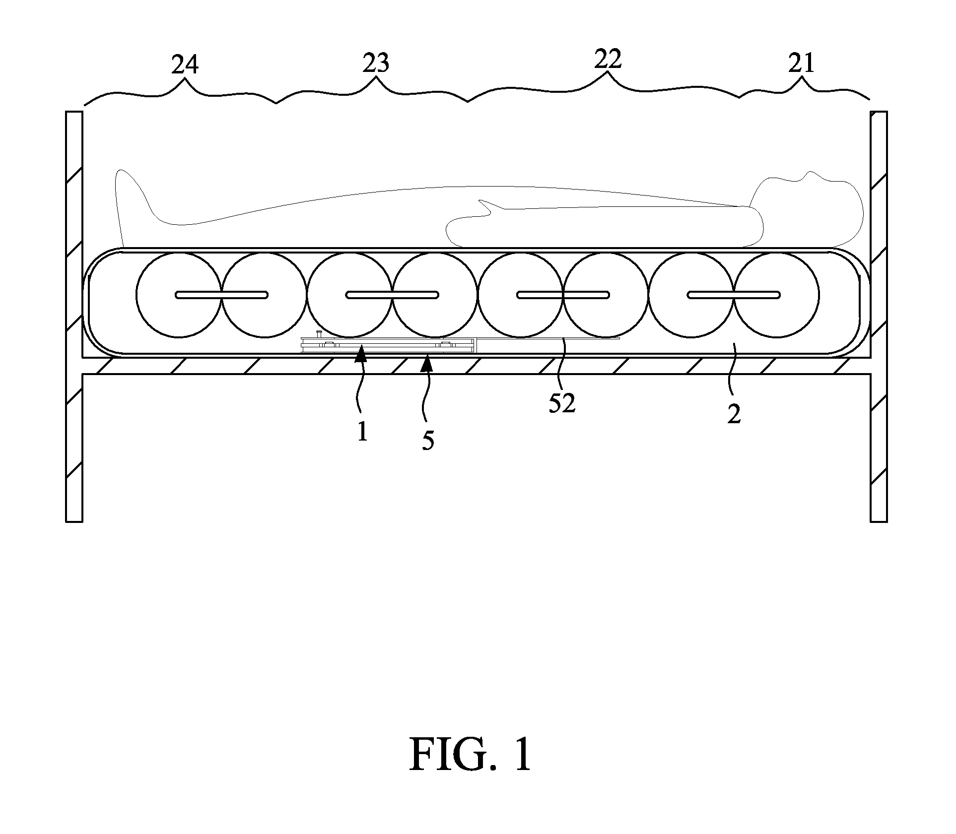
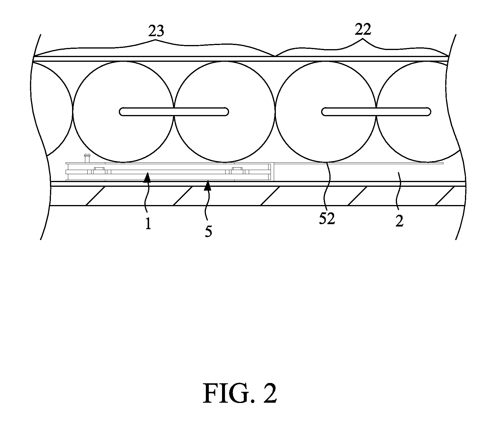
[0032]As shown in FIG. 1 and FIG. 2, the magnetic induction pad 1 of the present invention may be set up in between the frame of a bed and a bed body 2, whereby the bed body 2 may include a head part area 21, an upper body area 22 that is in continuous connection with the head part area 21, a buttock part area 23 that is in continuous connection with the upper body area 22, and a lower body area 24 that is in continuous connection with the buttock part area 23. It is clear from FIG. 1 that, and in accordance with a preferred exemplary embodiment of the present invention, the magnetic induction pad 1 of the present invention may be set up in between the frame o...


PUM


Abstract

The present invention provides a magnetic induction pad. The magnetic induction pad includes a deformation body and a plurality of magnetic induction modules. The interior of the deformation body includes a filling space that is in connection with the outside via at least one gas nozzle. The external of the deformation body includes a first surface and a second surface. The first surface and the second surface include a plurality of first bag bodies and a plurality of second bag bodies, respectively. The plurality of first bag bodies are mutually arranged to form a first pattern. The plurality of second bag bodies are mutually arranged to form a second pattern that are the same as the first patterns, so as to enable the position of each of the plurality of first bag bodies on the first surface to have a corresponding arrangement to each of the plurality of second bag bodies of the second surface. The plurality of magnetic induction modules includes a group of magnetic members and a group of induction members. The group of magnetic members and the group of induction members are respectively arranged at the corresponding positions within the plurality of first bag bodies and the plurality of second bag bodies. According to the magnetic theory, it enables the determination of whether a human body lies down on a bed, on the basis of the degree of compression of the magnetic induction pad between the plurality of magnetic induction modules.

Description

FIELD OF THE INVENTION[0001]The present invention relates generally to a magnetic induction pad, and more particularly, the present invention relates to a magnetic induction pad that is placed between a bed frame and a bed; in other words, it is for determining whether a human body has lain down on a bed based on the magnetism between the magnetic elements.BACKGROUND OF THE INVENTION[0002]For the majority of patients, including the patients with reduced mobility, those with physical disabilities or the elderly, resting in bed is a must in order for their health to be nursed back. Since these patients need to rest in bed for long periods of time, as such, surveillance cameras and surveillance equipment have often been set up by a lot of care centers, rehabilitation centers and hospitals, in order to ensure that the patient is still resting on the bed at specific times of the day. In addition, the surveillance cameras and surveillance equipment are also set up to help determine whethe...

Claims


Application Information

Patent Timeline
Patent Type & Authority Patents(United States)
IPC IPC(8): G01B7/14G01V3/10G01D5/20A61B5/11
CPCG01V3/10A61B5/1116A61B5/1126G01D5/2006G01V3/081A61B5/6843A61B5/6892A61B5/1115A61B2562/0223A61B2562/0252G01D5/204
Inventor SHIH, PAO MING
Owner CAREMED SUPPLY
Why Eureka
Try Eureka