
Tool for abrasive flow machining of airfoil clusters

a technology of airfoil clusters and tools, which is applied in the direction of polishing machines, metal-working equipment, manufacturing tools, etc., can solve the problems of abrasive wear and structural damage, difficult-to-reach surfaces, and small control of the flow and velocity of abrasive media over hard-to-reach areas of parts

Active Publication Date: 2017-01-24
RTX CORP
View PDF11 Cites 9 Cited by
  • Summary
  • Abstract
  • Description
  • Claims
  • Application Information

AI Technical Summary

Benefits of technology

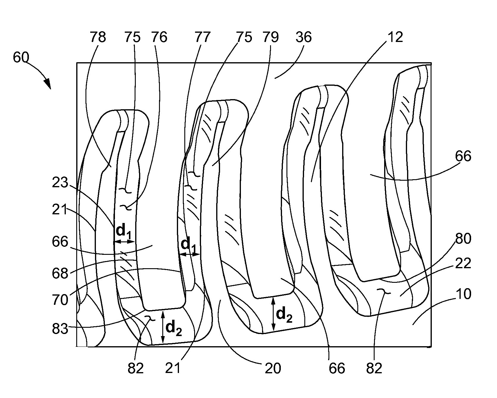
[0025]In accordance with another aspect of the present disclosure, a method for using a tool for the abrasive flow machining of an airfoil cluster is disclosed. The method may comprise assembling the airfoil cluster with the tool by inserting a prong of the tool between an adjacent pair of airfoils of the airfoil cluster to create at least one channel therebetween. The channel may allow the flow of an abrasive media therethrough. The method may further comprise initiating the flow of the abrasive media through the at least one channel. The curvature and widths of the channel may assist in controlling the direction and velocity of the flow of the abrasive media over surfaces of the airfoil cluster.

Problems solved by technology

In particular, current fixtures for abrasive flow polishing of airfoil clusters are designed to hold the part in position but may do little to control and guide the flow and velocity of the abrasive media over hard to reach areas of the part.
As a result, certain surfaces of the airfoil cluster may receive more surface polishing and more difficult to reach surfaces may be left with non-conforming surface roughness.
Moreover, current abrasive flow polishing methods may direct abrasive media directly at the certain regions of the airfoils (e.g., the leading edges) and this may lead to abrasive wear and structural damage in some cases.

Method used


Image

  • Tool for abrasive flow machining of airfoil clusters
  • Tool for abrasive flow machining of airfoil clusters
  • Tool for abrasive flow machining of airfoil clusters

Examples


Embodiment Construction

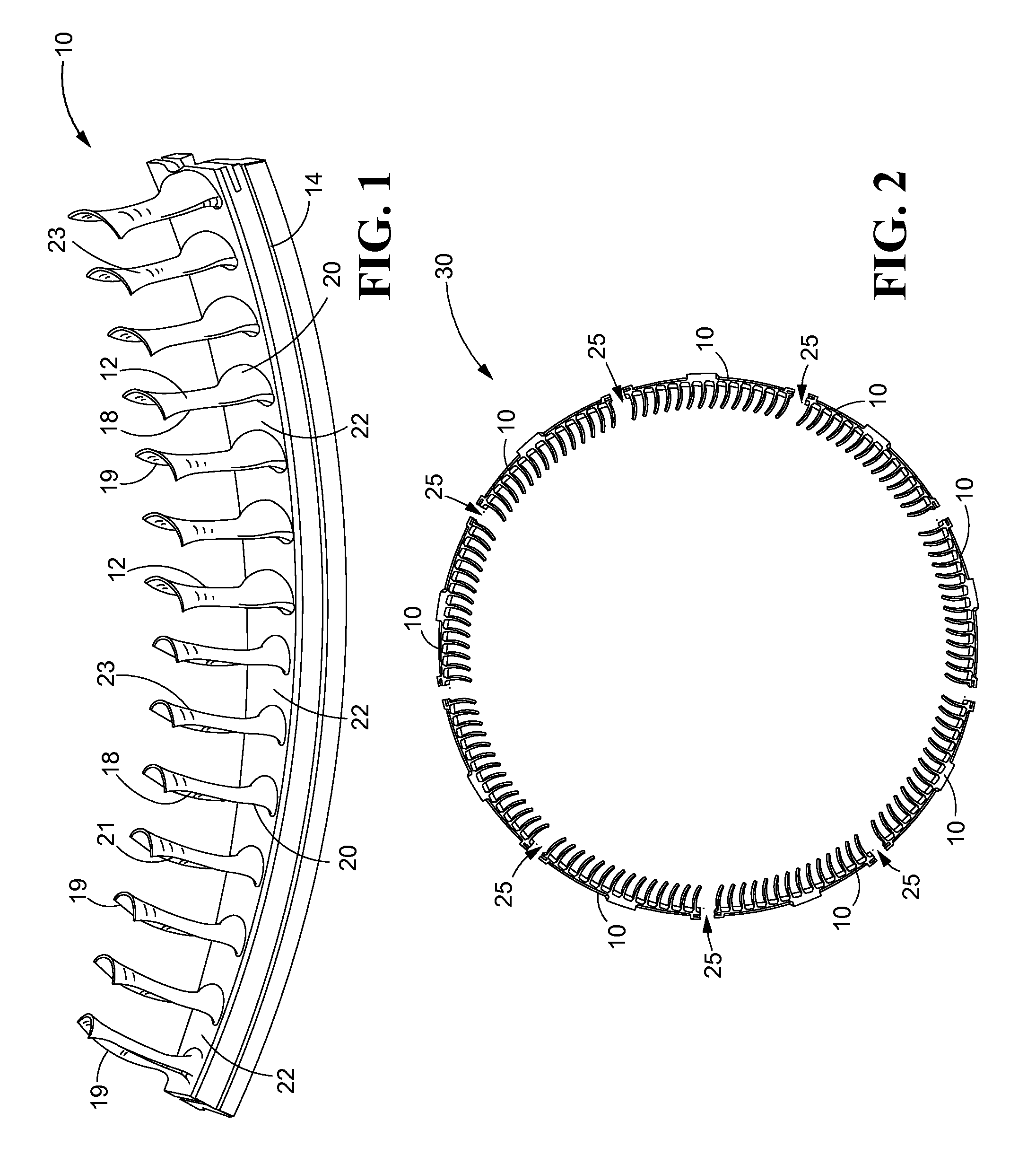
[0038]Referring now to the drawings, and with specific reference to FIG. 1, an airfoil cluster 10 is shown. The airfoil cluster 10 may consist of a plurality of airfoils 12 attached to a supporting rail 14 to form an integral piece or a unitary structure. Alternatively, the airfoils 12 and the supporting rail 14 may be formed separately and may assemble to form the airfoil cluster 10. In any event, each of the airfoils 12 may have a leading edge 18, a trailing edge 19, and a root radii 20 near the base of the airfoils 12, as shown. In addition, each of the airfoils 12 may have a concave surface 21 (pressure side of airfoil) and a convex surface 23 (suction side of airfoil). Between each adjacent pair of airfoils 12 may be a platform 22 along the upper surface of the support rail 14, as shown.

[0039]A plurality of the airfoil clusters 10 may assemble and connect to each other at connection points 25 to form an airfoil assembly 30 which may have an annular structure, as shown in FIG. 2...


PUM


Abstract

A tool for use during the abrasive flow polishing of an airfoil cluster in an abrasive flow machine is described. The tool may comprise a body and prongs extending from the body. Each prong of the tool may be configured to insert between an adjacent pair of airfoils of the airfoil cluster to create at least one channel therebetween. The channel may allow the flow of an abrasive media therethrough.

Description

CROSS-REFERENCE TO RELATED APPLICATION[0001]This patent application is a US National Stage under 35 U.S.C. §371, claiming priority to International Application No. PCT / US2013 / 076462 filed on Dec. 19, 2013, which claims priority under 35 U.S.C. §119(e) to U.S. Patent Application Ser. Nos. 61 / 904,124 filed on Nov. 14, 2013 and 61 / 800,697 filed on Mar. 15, 2013.FIELD OF DISCLOSURE[0002]The present disclosure generally relates to tools for abrasive flow polishing and, more specifically, relates to tools for abrasive flow polishing of airfoil clusters for gas turbine engines.BACKGROUND[0003]Abrasive flow polishing is a process that may be used for the surface polishing of metal parts prior to their distribution. The method has been found to be advantageous for the surface finishing and polishing of manufactured parts having complex structural features such as internal passages and / or buried cavities that are difficult to access by other surface finishing techniques. The process may take ...

Claims


Application Information

Patent Timeline
Patent Type & Authority Patents(United States)
IPC IPC(8): B24B31/10B24B31/116B24B19/14
CPCB24B31/116B24B19/14
Inventor BECKMAN, MICAHMASIUKIEWICZ, DAVID KRZYSZTOF
Owner RTX CORP
Learn More