Optical incoupling for touch-sensitive systems

a touch-sensitive system and optical incoupling technology, applied in the field of touch-sensitive systems, can solve the problems of difficult optical access to the edge surface, difficult and/or costly to achieve, and add to the footprint of the touch system, so as to achieve efficient and robust coupling of light and reduce dependen

Active Publication Date: 2017-01-24
FLATFROG LAB
View PDF42 Cites 35 Cited by
  • Summary
  • Abstract
  • Description
  • Claims
  • Application Information

AI Technical Summary

Benefits of technology

[0012]It is an object of the invention to at least partly overcome one or more of the above-identified limitations of the prior art. One objective is thus to provide an efficient and robust coupling of light into a light transmissive panel of an optical touch system, which is less dependent on the quality of the edge surface and which allows the light to propagate by total internal reflection inside the panel.
[0018]The use of a sheet-like surface portion enables simple integration of the surface portion into the top or bottom surface of the panel, by the microstructure being directly formed in the top or bottom surface, so as to define a robust and durable incoupling site.
[0019]Another simple way of defining a compact and robust incoupling site is to manufacture and attach a dedicated sheet-like incoupling element, which defines the microstructured surface portion, to the top or bottom surface of the light transmissive panel. Such a sheet-like incoupling element may be so thin and flexible that it is able to absorb any shear forces that occur in the interface between the incoupling element and the light transmissive panel, e.g. caused by the above-mentioned difference in thermal expansion. Thereby, the sheet-like incoupling element may be firmly and robustly attached to the panel.
[0021]As a further advantage over a conventional wedge, the inventive implementation of the incoupling site enables additional optical functionality to be embedded in the microstructured surface portion, at low cost and little added complexity. For example, the microstructured surface portion may embed at least one of a refractive function, a diffractive function and a diffusive function into its light receiving surface, e.g. by proper design of the above-mentioned facets, and it may even be possible to tailor this additional optical functionality in different parts of the light receiving surface. The provision of such additional optical functionality may further improve the performance of the touch-sensitive apparatus, at the cost of minimal structural changes.
[0023]A second aspect of the invention is an optical coupling element for coupling light into a light transmissive panel in a touch-sensitive apparatus, wherein the light transmissive panel comprises top and bottom surfaces and is arranged to propagate light by total internal reflection from an incoupling site to an outcoupling site, wherein the optical coupling element is formed as a film of light transmissive plastic material, which film comprises a micro-structured surface portion and an attachment surface opposite to the micro-structured surface, the film being adapted for attachment to one of the top and bottom surfaces so as to form at least part of the incoupling site, by the micro-structured surface portion being arranged to transmit light that has an angle of incidence enabling light propagation by total internal reflection inside the panel. Such an optical coupling element is a light-weight component that may be conveniently attached to the top and / or bottom surface of a light transmissive panel so as to define a space-efficient and robust incoupling site that is able to efficiently couple light into the panel for propagation by TIR.
[0024]A third aspect of the invention is an optical touch panel for a touch-sensitive apparatus, wherein the optical touch panel comprises top and bottom surfaces and is arranged to propagate light by total internal reflection from an incoupling site to an outcoupling site, wherein the optical touch panel further comprises a micro-structured surface portion which is formed on one of the top and bottom surfaces to define the incoupling site and which is configured to transmit light having an angle of incidence that enables light propagation by total internal reflection inside the panel. Such an optical touch panel may be provided as a unitary component for installation in the touch-sensitive apparatus. The incoupling site may be defined to efficiently couple light into the panel for propagation by TIR by means of the microstructured surface portion which may be implemented as a space-efficient and robust feature on the top and / or bottom surface.

Problems solved by technology

This may be difficult and / or costly to achieve, especially if the panel is thin and / or manufactured of a comparatively brittle material such as glass.
Incoupling via the edge surface may also add to the footprint of the touch system.
Furthermore, it may be difficult to optically access the edge surface if the panel is attached to a mounting structure, such as a frame or bracket, and it is also likely that the mounting structure causes strain in the edge surface.
Such strain may affect the optical quality of the edge surface and result in reduced incoupling performance.
Such a wedge may add significant thickness and weight of the system.
Even a small or local detachment of the wedge may cause a significant decrease in the performance of the system.
However, if the touch system requires more than one sheet of light to be injected via the incoupling site, such that the light transmitted via the incoupling site has more than one main direction in the plane of the panel (i.e. as seen in a plan view of the touch surface), the joints between the wedges may interfere with (e.g. reflect) the incoming light and cause a significantly reduced performance of the system.
However, the skilled person realizes that the thickness of the sheet-like incoupling element may be optimized in view of the material and structure of the sheet-like element, the expected amount of shear forces, the required durability of the incoupling site, manufacturability issues, etc.

Method used


Image

  • Optical incoupling for touch-sensitive systems
  • Optical incoupling for touch-sensitive systems
  • Optical incoupling for touch-sensitive systems

Examples


Embodiment Construction

[0037]For the sole purpose of explaining principles of the present invention, the following disclosure will be given with respect to a specific type of touch-sensitive apparatus or touch system in which beams are injected into and swept across a light transmissive panel, and touching objects are detected based on the amount of light that is received at an opposite end of the panel. This type of touch system is also denoted “scanning FTIR system” herein.

[0038]Throughout the description, the same reference numerals are used to identify corresponding elements.

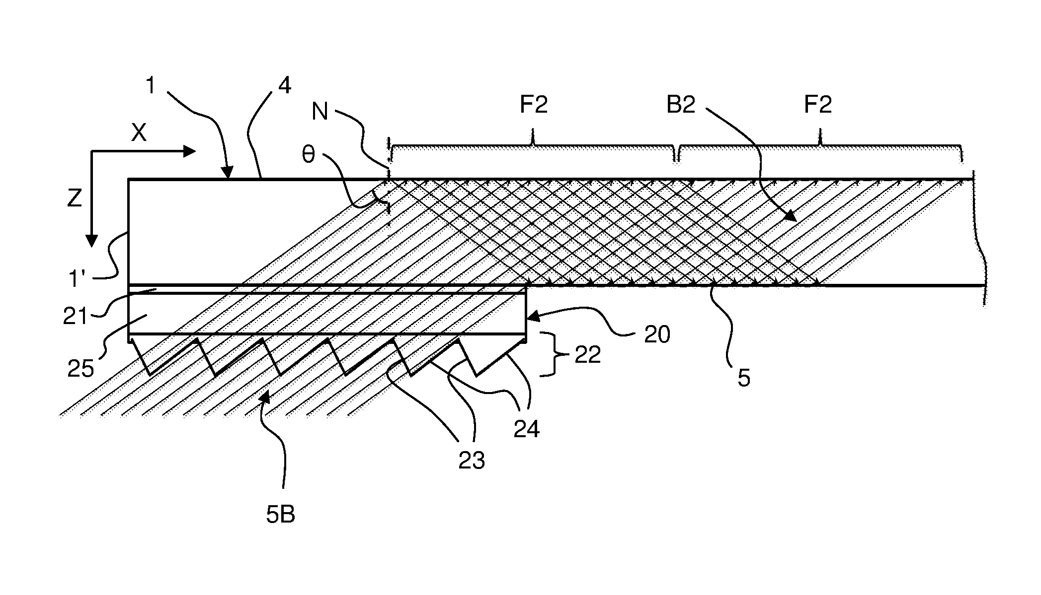
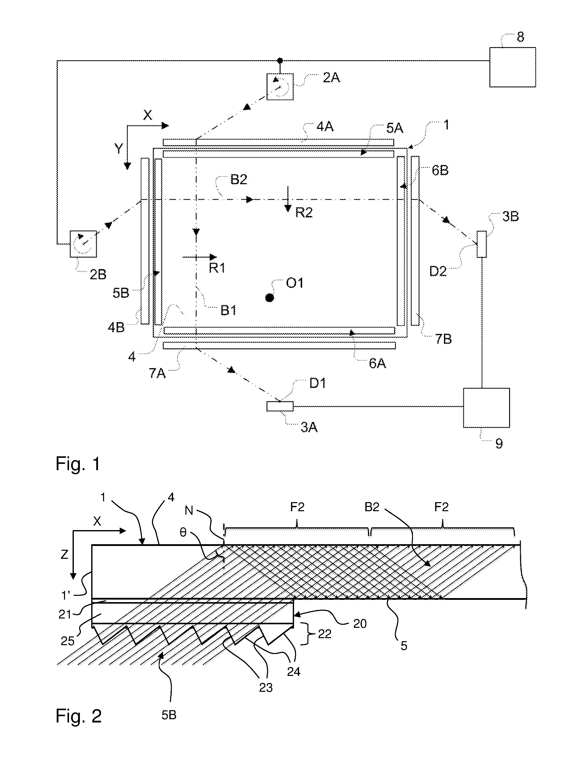
[0039]FIG. 1 is a top plan view of a scanning FTIR system. The system includes a light transmissive panel 1, two light-emitting input scanners 2A, 2B and two light sensors 3A, 3B. The panel may be planar or curved and defines two opposite and generally parallel surfaces 4, 5 (see FIG. 2), which are connected by a peripheral edge surface 1′ (FIG. 2). A radiation propagation channel is provided between the top and bottom surfaces 4,...


PUM


Abstract

A touch-sensitive apparatus comprises a light transmissive panel, an illumination arrangement and a detection arrangement. The illumination arrangement is configured to couple light into the panel via an incoupling site such that the light propagates by total internal reflection in opposite top and bottom surfaces of the panel and such that an object touching the top or bottom surface causes a change in the propagating light. The detection arrangement comprises a light detector arranged to detect the change in the propagating light. A compact and robust incoupling site is defined by a sheet-like micro-structured surface portion which is fixedly arranged on one of the top and bottom surfaces and configured to transmit light having an angle of incidence that enables light propagation by TIR inside the panel.

Description

CROSS-REFERENCE TO RELATED APPLICATIONS[0001]This application is the national phase under 35 U.S.C. §371 of PCT International Application No. PCT / SE2012 / 050086 which has an International filing date of Jan. 30, 2012, which claims priority to Swedish patent application number 1150071-7 filed Feb. 2, 2011 and to U.S. provisional patent application No. 61 / 438,675 filed Feb. 2, 2011.TECHNICAL FIELD[0002]The present invention relates to touch-sensitive systems that operate by light transmission through light transmissive panels, and in particular to optical solutions for coupling light into such panels.BACKGROUND ART[0003]The prior art comprises different types of touch-sensitive systems that operate by transmitting light inside a solid light transmissive panel, which is defined by two parallel boundary surfaces connected by a peripheral edge surface. Specifically, light is injected into the panel so as to propagate by total internal reflection (TIR) between the boundary surfaces. An obj...

Claims


Application Information

Patent Timeline
Patent Type & Authority Patents(United States)
IPC IPC(8): G06F3/042
CPCG06F3/0421G06F2203/04103G06F2203/04109G06F3/042G02B6/0016
Inventor CRAVEN-BARTLE, THOMASBERGSTROM, HAKAN
Owner FLATFROG LAB
Why Eureka
Try Eureka