Light source device for endoscopic or exoscopic applications

a technology for exoskeleton and light source device, which is applied in the direction of application, lighting and heating apparatus, lighting support device, etc., can solve the problems of low radiant capacity, dimension and modular capacity, and the degree of effectiveness or power requirement of waste heat, and achieve the effect of alternating coupling very quickly

Active Publication Date: 2011-09-29
KARL STORZ GMBH & CO KG
View PDF4 Cites 15 Cited by
  • Summary
  • Abstract
  • Description
  • Claims
  • Application Information

AI Technical Summary

Benefits of technology

[0027]The light source device described here makes possible, for example, a combination of two light sources with different radiation characteristics, in particular with different size of the light-emitting surface and/or with different divergence of the emitted light, and a simultaneous or alternating coupling of their light into the same illuminating beam path. For example, the light of a light diode or of an array of light diodes with a relatively large light-emitting surface can be united or mixed or combined with the light of a laser diode or another diode laser, which can be bundled onto a very small surface and can be coupled with minor losses into a lightwave conductor.
[0028]The light source device makes possible in addition an alternating coupling of light from the first light source and light from the second light source into the illuminating beam path without being forced to optically modify the beam path. Therefore, light from ...

Problems solved by technology

Disadvantages of the aforementioned light sources concern the degree of effectiveness or power requirement and waste heat, dimension and modular capacity.
A disadvantage of a light diode, in comparison to a conventional light source, consists in the fact that not only the radiant flux Phi generated by it, but also the specific irradiance R (in Wm−2) and the emittance B=d2Phi/dA d Omicron cos(0) (in Wm−2 steradians−1) are smaller or definitely smaller tha...

Method used


Image

  • Light source device for endoscopic or exoscopic applications
  • Light source device for endoscopic or exoscopic applications
  • Light source device for endoscopic or exoscopic applications

Examples


Embodiment Construction

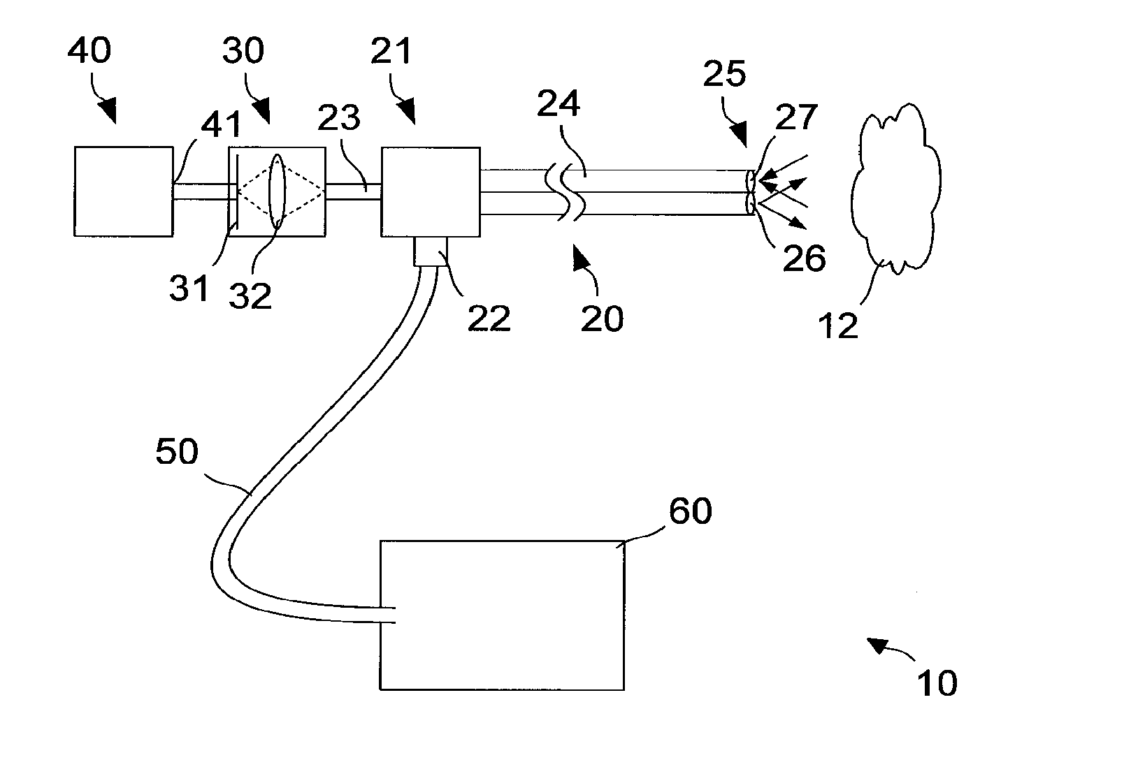
[0086]FIG. 1 shows a schematic view of an endoscopy system 10 for observing and / or optically recording an object 12. The endoscopy system 10 includes an endoscope 20. A coupling 22 for a light conductor cable and a coupling 23 for a video camera are positioned on the proximal end 21 of the endoscope 20. A rigid or flexible shaft 24 extends from the proximal end 21 to a distal end 25 of the endoscope 20. On the distal end 25 the endoscope 20 comprises a light outlet window 26 and a light inlet window 27.

[0087]The endoscope 20 is coupled with a video camera 30 by the coupling 23. The video camera 30 includes a light-sensitive image sensor 31 and an object lens 32. Contrary to the depiction in FIG. 1 and alternatively to it, instead of the video camera 30, an eyepiece can be provided through which an image of the object 12 recorded by the endoscope 20 can be observed directly by the human eye.

[0088]The proximal end 21 of the endoscope 20 is coupled with a light source device 60 by mean...


PUM


Abstract

A light source device for endoscopic or exoscopic applications includes a flat first light source, a second light source, an illuminating beam path that is configured to provide a first light beam emanating from the first light source for an endoscopic or exoscopic application, and a coupling device to couple a second light beam from the second light source into the illuminating beam path, whereby the coupling device is configured in such a way that at the coupling site the cross-section surface of the second light beam is smaller than the cross-section surface of the first light beam.

Description

CROSS-REFERENCE TO RELATED APPLICATIONS[0001]The present application claims priority of German patent application No. 10 2010 013 307.8 filed on Mar. 29, 2010, the content of which is incorporated herein by reference.FIELD OF THE INVENTION[0002]The present invention relates to a light source device with at least two light sources for endoscopic or exoscopic applications.BACKGROUND OF THE INVENTION[0003]To generate light to illuminate an object that is to be observed by an endoscope, tungsten halogen lamps and especially gas discharge lamps are primarily used, for example xenon-short arc lamps, other halide short arc lamps and high-pressure mercury vapor lamps. These light sources are customarily combined in a light source device with their own power source, a control or regulation filter and a blower for discharging waste heat. The light source device is produced as a separate unit from its own endoscope and is connected with the proximal end of the endoscope by a light conductor ca...

Claims


Application Information

Patent Timeline
IPC IPC(8): F21V5/00F21S4/00
CPCA61B1/0638A61B1/0669A61B1/0684A61B1/07A61B1/0661A61B1/063A61B1/0653A61B1/0676A61B1/043A61B1/0605
Inventor IRION, KLAUS-MARTINHINDING, THOMASGOEBEL, WERNER
Owner KARL STORZ GMBH & CO KG
Why Eureka
Try Eureka