Positioning method of photoelectric conversion device, and liquid ejecting apparatus

a technology of photoelectric conversion device and liquid ejector, which is applied in the direction of microlithography exposure apparatus, semiconductor devices, printing, etc., can solve the problems of reducing the accuracy of the image that is acquired by the imaging device that is housed in the lens barrel member, reducing the accuracy of the image acquisition accuracy, and reducing the accuracy with which the image is acquired. , to achieve the effect of reliable determination of the movement amoun

Active Publication Date: 2017-01-24
SEIKO EPSON CORP
View PDF6 Cites 0 Cited by
  • Summary
  • Abstract
  • Description
  • Claims
  • Application Information

AI Technical Summary

Benefits of technology

[0010]Embodiments of the invention relate to a method for positioning a photoelectric conversion device, and to a liquid ejecting apparatus in which the precision of an image to be acquired is not easily reduced or compromised.
[0014]The position of the photoelectric conversion device at which the photoelectric conversion device detects a side of the opening of the light shielding member and another side opposing the side is acquired by moving the photoelectric conversion device in a direction orthogonal to the optical axis of the optical member and detecting the sides of the rectangle of the irradiation region of the light corresponding to the sides of the opening of the light shielding member. Therefore, in comparison with a case in which the irradiation region of the light is circular, the photoelectric conversion device can easily detect the sides of the opening of the light shielding member. In relation to the position of the photoelectric conversion device, the position at which the center position of the optical member in a direction orthogonal to the optical axis is aligned with the center of the rectangular opening of the light shielding member is calculated precisely. Therefore, if the photoelectric conversion device is positioned in such a position such that a center of the photo conversion device is aligned with the center of the opening in the light shielding member, the precision of the acquired image is not easily reduced.
[0016]According to embodiments of the liquid ejecting apparatus, the light shielding member can suppress light from passing through the light shielding member except at the opening formed therein. Desired light passes through the opening of the light shielding member. Therefore, the stray light caused by scattering or the like of light on the inside wall of the lens barrel is suppressed from passing through the opening of the light shielding member. The light shielding member can effectively block the interior of the lens barrel except for the area associated with the opening in the light shielding member. As a result, the body of the light shielding member can block, absorb or otherwise suppress stray light. As a result, the imaging device receives light in which the stray light has been suppressed. In other words, the imaging device receives less light and scattered light is suppressed from reaching the imaging device by the light shielding member or by a portion or body of the light shielding member. Therefore, the precision of the image that is acquired by the imaging device is not easily reduced or deteriorated.
[0018]According to embodiments of the liquid ejecting apparatus, the stray light caused by scattering or the like of the light impinging on the inside wall of the lens barrel is suppressed from passing through the opening of the light shielding member due to a portion or body of the light shielding member (except for the opening of the light shielding member) absorbing the light that is radiated on the portion or body of the light shielding member. Therefore, the precision of the image that is acquired by the imaging device is further not easily reduced or deteriorated.
[0020]According to embodiments of the liquid ejecting apparatus, the surface of the light shielding member may be sprayed or the like with dye. The light absorbing properties of the light shielding member may be due to being black because of being sprayed or the like with dye. Therefore, it is possible to suppress the stray light with a simple configuration.
[0022]According to embodiments of the liquid ejecting apparatus, in addition to the scattering of light by the inside wall of the lens barrel, the stray light caused by scattering or the like is suppressed from passing through the opening of the light shielding member. Therefore, stray light is suppressed while desired light passes through the opening, and the image that is acquired by the imaging device becomes more stable and the determination of the movement amount is more reliable.

Problems solved by technology

However, the precision of the image that is acquired by the imaging device that is housed in the lens barrel member is reduced by stray light.
In a positioning step of the imaging device in which the center position of the imaging device is aligned to the optical axis of the optical member based on an output signal of the imaging device, which is output according to the light with which the imaging device is irradiated, there is a concern that misalignment will increase when the precision of the image that is acquired by the imaging device is reduced.
The scattered light can reduce the precision with which the image is acquired.
When the precision of the image that is acquired by the imaging device of the imaging unit is reduced or is deteriorated, for example by scattered light, there is a concern that the precision of the movement amount of the paper detected by the detection unit will be reduced.
Note that, because the imaging unit that is mounted to the printer of JP-A-2013-119439 is not particularly made in consideration of the precision of the image that is acquired by the imaging device being reduced due to stray light in this manner, the imaging unit is considered to include the same problem as that described above.
Therefore, if the photoelectric conversion device is positioned in such a position such that a center of the photo conversion device is aligned with the center of the opening in the light shielding member, the precision of the acquired image is not easily reduced.
Therefore, the precision of the image that is acquired by the imaging device is not easily reduced or deteriorated.
Therefore, the precision of the image that is acquired by the imaging device is further not easily reduced or deteriorated.

Method used


Image

  • Positioning method of photoelectric conversion device, and liquid ejecting apparatus
  • Positioning method of photoelectric conversion device, and liquid ejecting apparatus
  • Positioning method of photoelectric conversion device, and liquid ejecting apparatus

Examples


Embodiment Construction

[0032]Hereinafter, description will be given of an ink jet printer, which is an example of a liquid ejecting apparatus, with reference to the drawings.

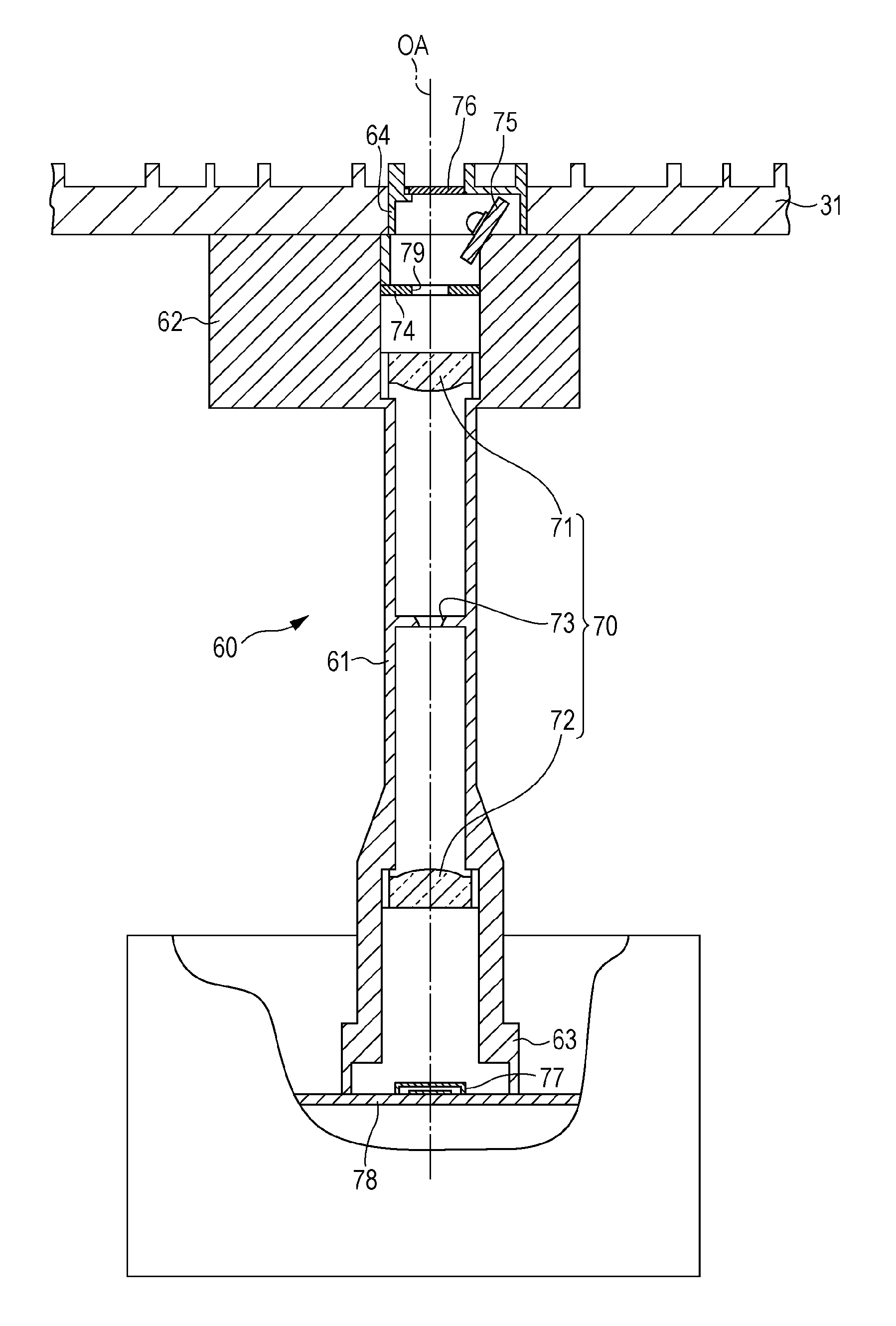
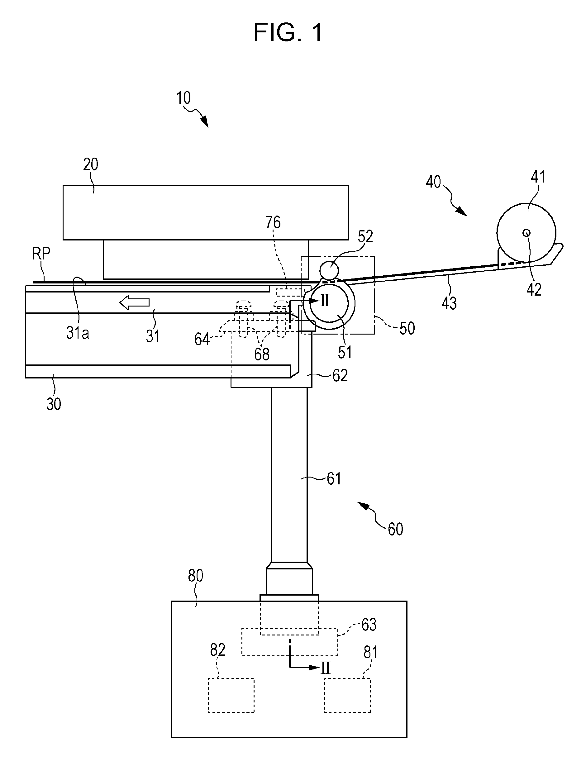
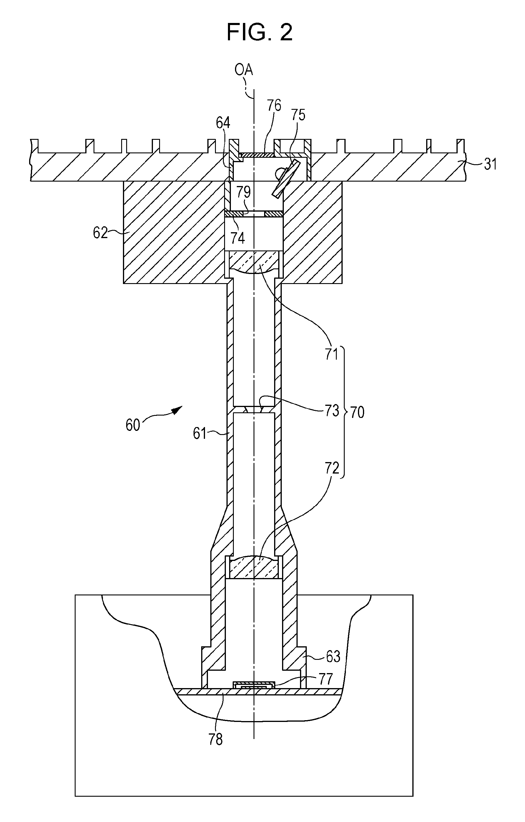
[0033]As illustrated in FIG. 1, a printer 10 may include a printing liquid ejecting unit 20 which serves as the liquid ejecting unit, a base section 30, a paper supply unit 40, a transport unit 50, an imaging unit 60, and a transport control unit 80 which serves as the control unit. The base section 30 may include a medium supporting portion 31 on the side opposing the printing liquid ejecting unit 20. The paper supply unit 40 may include a paper holding portion 41, a roll shaft 42, and a paper case 43. The paper holding portion 41 holds long-sheet shaped paper RP, which is an example of a medium which is wound around the roll shaft 42 in a roll shape. The paper case 43 forms a transport path which guides the paper RP, which is unwound and fed out from the roll state by the roll shaft 42 rotating, to the transport unit 50. The paper s...


PUM

PropertyMeasurementUnit
movementaaaaaaaaaa
transparentaaaaaaaaaa
optical axisaaaaaaaaaa

Abstract

A positioning method of a photoelectric conversion device (an imaging device) includes irradiating an optical member with light and receiving light which passes through an opening of a light shielding member and the optical member with the photoelectric conversion device. The photoelectric conversion device is moved in a direction orthogonal to an optical axis of the optical member and a first position at which the photoelectric conversion device detects a side of an opening and a second position at which the photoelectric conversion device detects another side opposing the side are acquired. A position of the photoelectric conversion device at which a center of the opening and a center position of the photoelectric conversion device are aligned based on the first position and the second position is determined. The photoelectric conversion device is fixed at the determined position.

Description

[0001]The present application claims priority to Japanese Patent Application No. 2014-071239 filed on Mar. 31, 2014, which is hereby incorporated by reference in its entirety.BACKGROUND[0002]1. Technical Field[0003]Embodiments of present invention relate to method for positioning a photoelectric conversion device, and a liquid ejecting apparatus that includes a photoelectric conversion device.[0004]2. Related Art[0005]An ink jet printer is known as an example of the liquid ejecting apparatus. The printer forms an image on paper by ejecting a printing liquid onto the paper. The printing liquid is an example of a liquid that is ejected from a liquid ejecting unit onto the paper. The printer includes a transport unit and the paper is an example of a medium which is transported a predetermined movement amount by a transport roller of the transport unit. Accordingly, the image in the transport direction of the paper is influenced by the precision of the movement amount of the paper or th...

Claims


Application Information

Patent Timeline
Patent Type & Authority Patents(United States)
IPC IPC(8): G03F7/20H01L31/0232H01L31/02B41J11/00
CPCH01L31/02016B41J11/0095H01L31/02327
Inventor IDE, MITSUTAKAKATAOKA, HIDEYUKIKOBAYASHI, HIROYUKI
Owner SEIKO EPSON CORP
Why Eureka
Try Eureka