Automated emergency notification system

a notification system and automatic technology, applied in the field of automatic notification system, can solve the problems of lack of coverage, lack of current or proposed solutions, and the inability to easily trigger the system when necessary, and achieve the effect of convenient and convenient activation

Active Publication Date: 2017-01-24
EASTERN DATACOMM LLC
View PDF11 Cites 3 Cited by
  • Summary
  • Abstract
  • Description
  • Claims
  • Application Information

AI Technical Summary

Benefits of technology

[0012]An aspect of an example embodiment in the present disclosure is to provide an emergency notification system that may be easily and conveniently activated to provide comprehensive and immediate warning notification throughout a facility. Accordingly, the present disclosure provides an emergency notification system that employs a notification system controller integrated with a telephone system and paging system. The telephone system has telephone extension handsets througho

Problems solved by technology

Mass shootings at schools and other institutions has become a frightening reality that has occurred with increasing frequency over the past several years.
Most currently available or proposed solutions fall short in the ease of triggering the system when necessary.
This problem sometimes stems from the difficulty of activation—such as by requiring cumbersome authentication or some other requirement that is difficult to carry out in the course of an emergency.
It may also stem from ‘lack of coverage’—where the physical locations from which the system can be activated are not always convenient to all areas where an emergency situation may be spotted.
As a result, when the system is inconvenient to activate, it greatly increases the possibility that lock down, shelter in place, or other emergency procedures, will not be initiated when necessary.
Many systems also fall short in the comprehensiveness of measures taken in response to its activation.
In particular, notification of the emergency situation might not reach all k

Method used


Image

  • Automated emergency notification system
  • Automated emergency notification system
  • Automated emergency notification system

Examples


Embodiment Construction

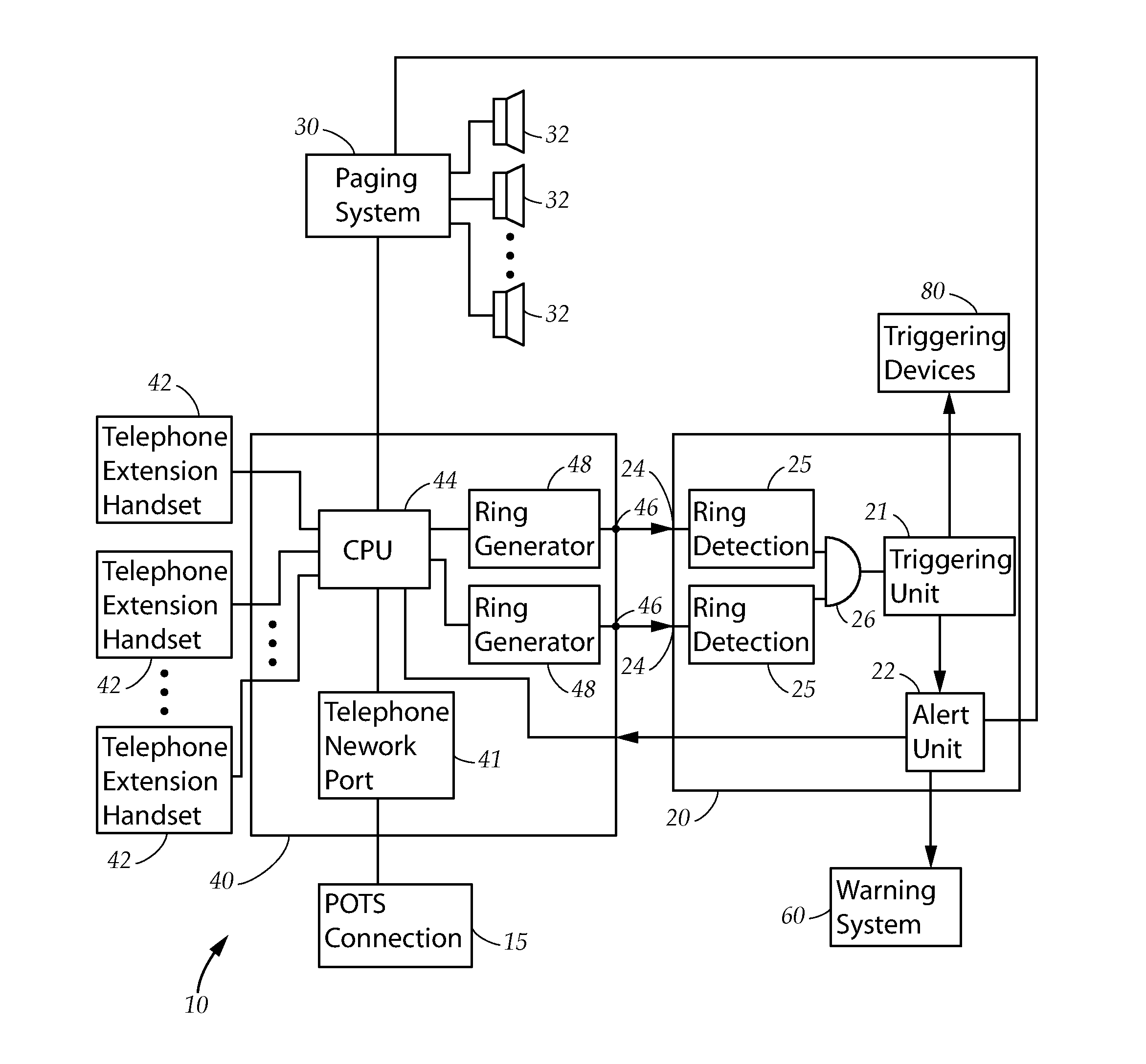
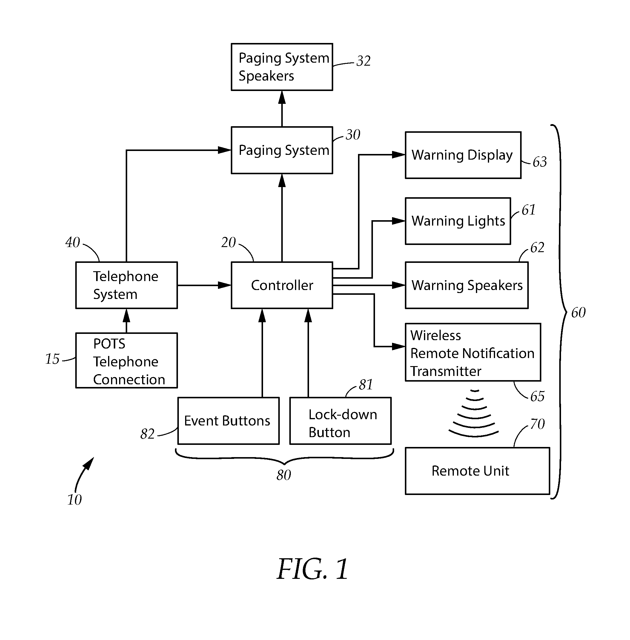
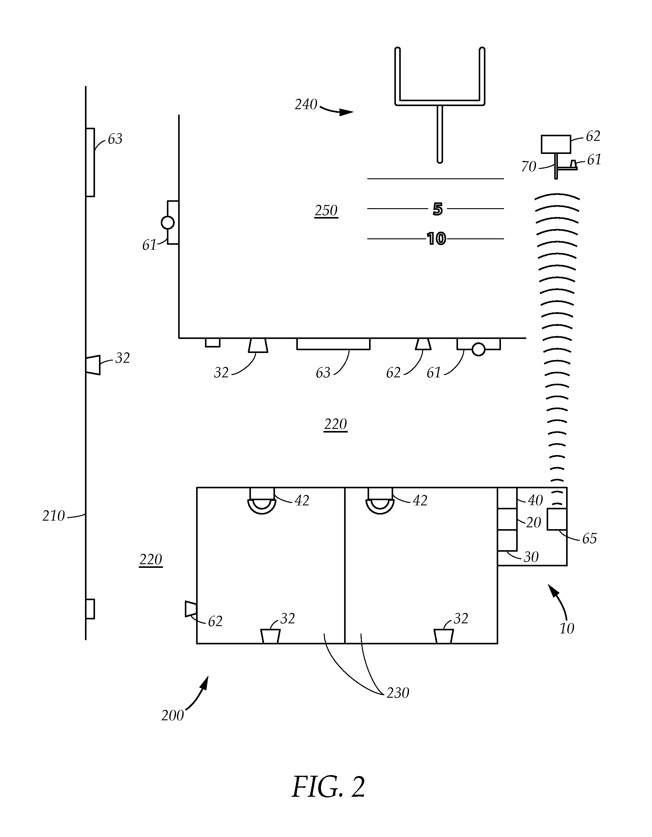
[0024]FIG. 1 illustrates an emergency notification system 10, having a notification system controller 20 that provides, facilitates, and orchestrates key functionality of the system 10. The emergency notification system 10 also has a paging system 30 and a telephone system 40 that are connected to the notification system controller 20. At least one triggering device 80 is connected to the controller 20 to initiate an alert condition. A warning system 60 is connected to the controller 20 to provide distributed notification when the alert condition is determined.

[0025]The telephone system 40 is connected to a POTS telephone network connection 15 that provides connectivity to telephonic devices worldwide through conventional ten digit domestic dialing, extended digit long distance dialing, or the like. Through this connection, warning notifications can be sent to telephones, cell phones, pagers, or any other telephonic device reachable through the POTS telephone network. In addition, i...


PUM


Abstract

An automated notification system for use in a facility, including a telephone system, a controller, a paging system, and a warning system. The warning system includes warning lights, warning speakers, and warning displays. The telephone system includes extension handsets, and the paging system includes paging speakers. The extension handsets, paging speakers, warning speakers, warning lights, and warning displays are distributed throughout the facility. An alert condition may be activated using one of the extension handsets or by an activation device within the facility. Upon detection of an alert condition, the controller actuates the warning system and uses the paging system to provide audible and visual warnings throughout the facility, and provides outgoing notification to emergency personnel through the telephone system. Remote units located in outlying areas around the facility are wirelessly signaled by the control unit to provide appropriate warnings in such locations.

Description

TECHNICAL FIELD[0001]The present disclosure relates generally to an automated notification system. More particularly, the present disclosure relates to integrating telephone and paging systems with other warning system devices in a facility to provide a comprehensive, automated emergency notification and warning system.BACKGROUND[0002]When an emergency situation occurs at a highly populated facility, such as a school, rapid and clear communication is often the difference between experiencing minimum and massive casualties. Scores of examples exist where casualties were directly attributed to a communication failure.[0003]Among the possible emergency situations that might arise, a mass shooting probably the most ominous. Mass shootings at schools and other institutions has become a frightening reality that has occurred with increasing frequency over the past several years. In response, schools have sought to take every available precaution and safety measure in preparation for the un...

Claims


Application Information

Patent Timeline
IPC IPC(8): H04M11/00H04M3/537H04M1/82H04Q1/30
CPCH04M3/537H04M1/82H04Q1/30H04M2203/658H04M2242/26H04Q2213/13374H04M3/02H04M2242/04H04M19/04H04M1/72418
Inventor HARNISCH, AL
Owner EASTERN DATACOMM LLC
Why Eureka
Try Eureka