Pressure relief valve for filter assembly

Inactive Publication Date: 2007-02-08
WIX FILTRATION
View PDF9 Cites 7 Cited by
  • Summary
  • Abstract
  • Description
  • Claims
  • Application Information

AI Technical Summary

Benefits of technology

[0009] The present invention provides a unique oil filter assembly including a pressure relief valve that is adaptable to wide variety of environments while maintaining ease of assembly and manufacture. The pressure relief valve of this invention also occupies a minimal amount of space within the filter assembly as compared to conventional valve arrangements.
[0013] The filter media itself is a solid block and has no center tube. The filter media is a solid pleated pocket design affixed to the cap member. In the preferred design, the filter element is square rather than round to increase surface area. The structure of the filter media eliminates the center tube and compression spring and bottom plate typically used inside the shell of a spin-on filter assembly; thus, the number of parts is reduced and assembly is simplified.

Problems solved by technology

This oil is circulated through the engine and carries contaminants such as metal particles, carbon particles and dirt which may cause harm to the engine.
However, a large volume of waste is still generated by disposing of the filter element.

Method used


Image

  • Pressure relief valve for filter assembly
  • Pressure relief valve for filter assembly
  • Pressure relief valve for filter assembly

Examples


Embodiment Construction

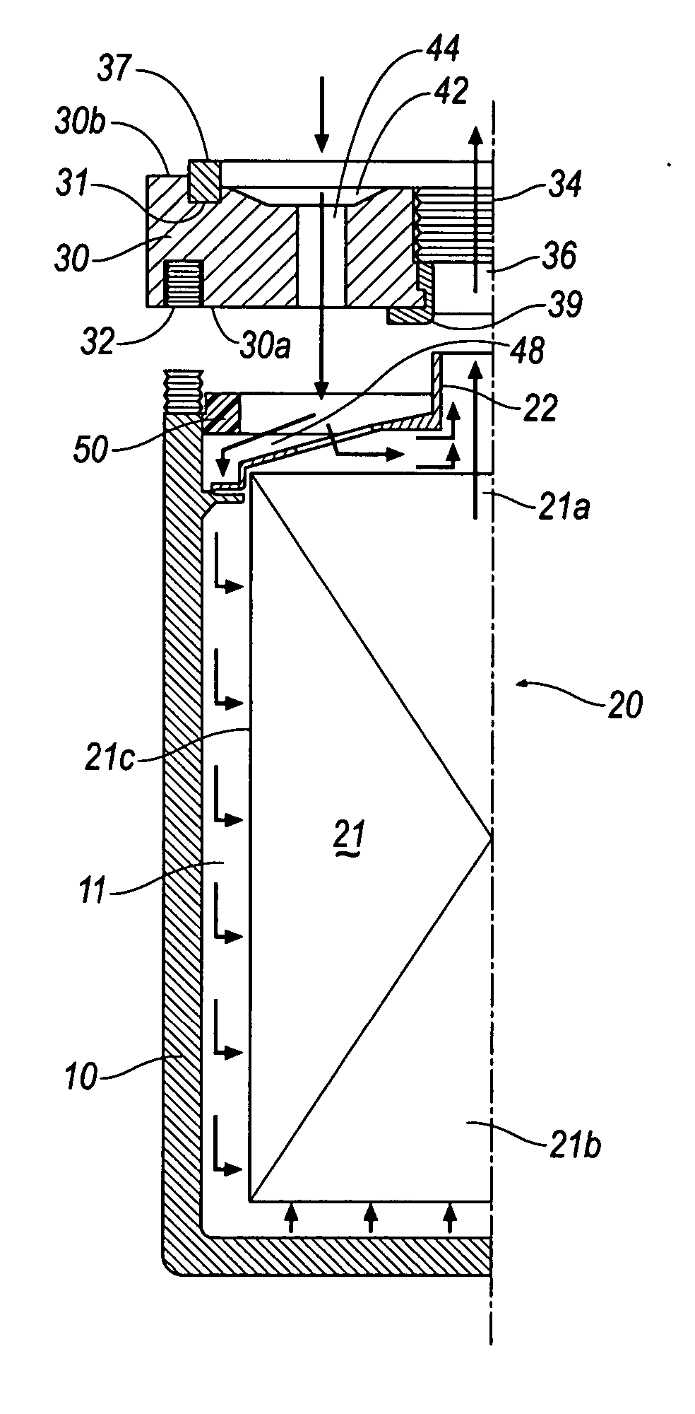
[0023] One form of the invention is illustrated and described herein as an oil filter on an engine. FIG. 1 illustrates reusable fluid filter comprising a housing shell 10, a filter element 20, and a threaded base 30.

[0024] As illustrated in FIG. 1, the threaded base 30 has external threads 32 and internal threads 34. External threads 32 are used to threadably mount the base 30 to a standard reusable filter housing shell 10. Internal threads 34 are machined to allow the fluid filter to be adapted to a wide variety of engines produced by various manufacturers. An engine block (not shown) typically has an oil filter stub (not shown) to allow a fluid filter to be threadably attached via internal threads 34. Filtered oil port 36 is formed in base 30 to allow filtered fluid to exit the reusable fluid filter after passing through the cap member 22. Threaded base 30 is designed to be an inexpensive device to allow the reusable oil filter to be adapted to a wide variety of engine blocks. In...


PUM

PropertyMeasurementUnit
Pressureaaaaaaaaaa
Sizeaaaaaaaaaa
Widthaaaaaaaaaa

Abstract

An oil filter assembly includes a pressure relief valve adaptable to wide variety of environments while maintaining ease of assembly and manufacture. The pressure relief valve of this invention also occupies a minimal amount of space within the filter assembly as compared to conventional valve arrangements. In the preferred embodiment, the three-piece filter system comprises a base, a deep pocket filtering media, and a housing shell. The unitary filtering media and cap member are formed as a replaceable component that seats into the housing shell without a center tube or other outside support. When the housing shell is threaded onto the base, the cap member is sandwiched between a ledge on the shell and a seal on the base. The pressure relief valve allows fluid to continue to flow in the event the filter element becomes clogged whereby the valve provides ease of assembly, reduced cost, and reduced valve size.

Description

RELATED APPLICATION [0001] This is a continuation of application Ser. No. 10 / 445,263, filed May 27, 2003.BACKGROUND OF THE INVENTION [0002] 1. Field of the Invention [0003] This invention relates to filters for filtering fluids such as engine oil, coolant, fuel, hydraulic or transmission fluid. [0004] 2. Description of Related Art [0005] Fluid filters are used to remove contaminants from fluid, such as engine oil. Internal combustion engines use oil to lubricate bearings and reduce friction. This oil is circulated through the engine and carries contaminants such as metal particles, carbon particles and dirt which may cause harm to the engine. In order to effectively lubricate the engine, engine oil is passed through a filter to remove the contaminants before the oil is recirculated into the engine. The typical oil filter is attached to an internal combustion engine at the oil filter receptacle. [0006] Engine oil passes through a discharge opening in the oil filter receptacle, into a...

Claims


Application Information

Patent Timeline
IPC IPC(8): B01D35/14
CPCB01D29/016B01D35/153B01D35/147Y10S210/17
Inventor CRAWFORD, BRIAN SCOTTADAMS, MICHAEL DAVID
Owner WIX FILTRATION
Why Eureka
Try Eureka