Method and apparatus for reducing far-end crosstalk in electrical connectors

a far-end crosstalk and electrical connector technology, applied in the field of systems for reducing far-end crosstalk (fext), can solve the problems of significant increase in unwanted noise, or electromagnetic coupling occurring between neighbor channels, imposed design and implementation difficulties, and increase the consumption of allocated real estate, so as to facilitate pcb trace routing, large consumption of pcb real estate, and stable power distribution through the connector

Active Publication Date: 2017-01-24
HIROSE ELECTRIC GROUP
View PDF8 Cites 2 Cited by
  • Summary
  • Abstract
  • Description
  • Claims
  • Application Information

AI Technical Summary

Benefits of technology

[0016]Examples of additional attributes of the implementations of the present disclosure may include, but are not limited to, space saving, ease of PCB trace routing and stable power distribution through the connector. Placing too many ground vias and signal vias that are spaced out will result in a large consumption of PCB real estate by the via field, a limited space for routing traces to escape vias, and a poor power distribution at the connector due to densely populated antipads on the power plane. With the example implementations describe herein, a fewer number of ground vias can be utilized to achieve sufficient FEXT at vias to offset FEXT from the connector, which is in many cases much larger than the vias.

Problems solved by technology

As a result, unwanted noise, or electromagnetic coupling occurring between neighbor channels significantly increases.
However, such related attempts have increased consumption of allocated real estate, imposed difficulty in design and implementation, and been relatively insufficient in reducing cumulative total FEXT, particularly in higher frequency systems.
Placing too many ground vias and signal vias that are spaced out will result in a large consumption of PCB real estate by the via field, a limited space for routing traces to escape vias, and a poor power distribution at the connector due to densely populated antipads on the power plane.

Method used


Image

  • Method and apparatus for reducing far-end crosstalk in electrical connectors
  • Method and apparatus for reducing far-end crosstalk in electrical connectors
  • Method and apparatus for reducing far-end crosstalk in electrical connectors

Examples


example implementation

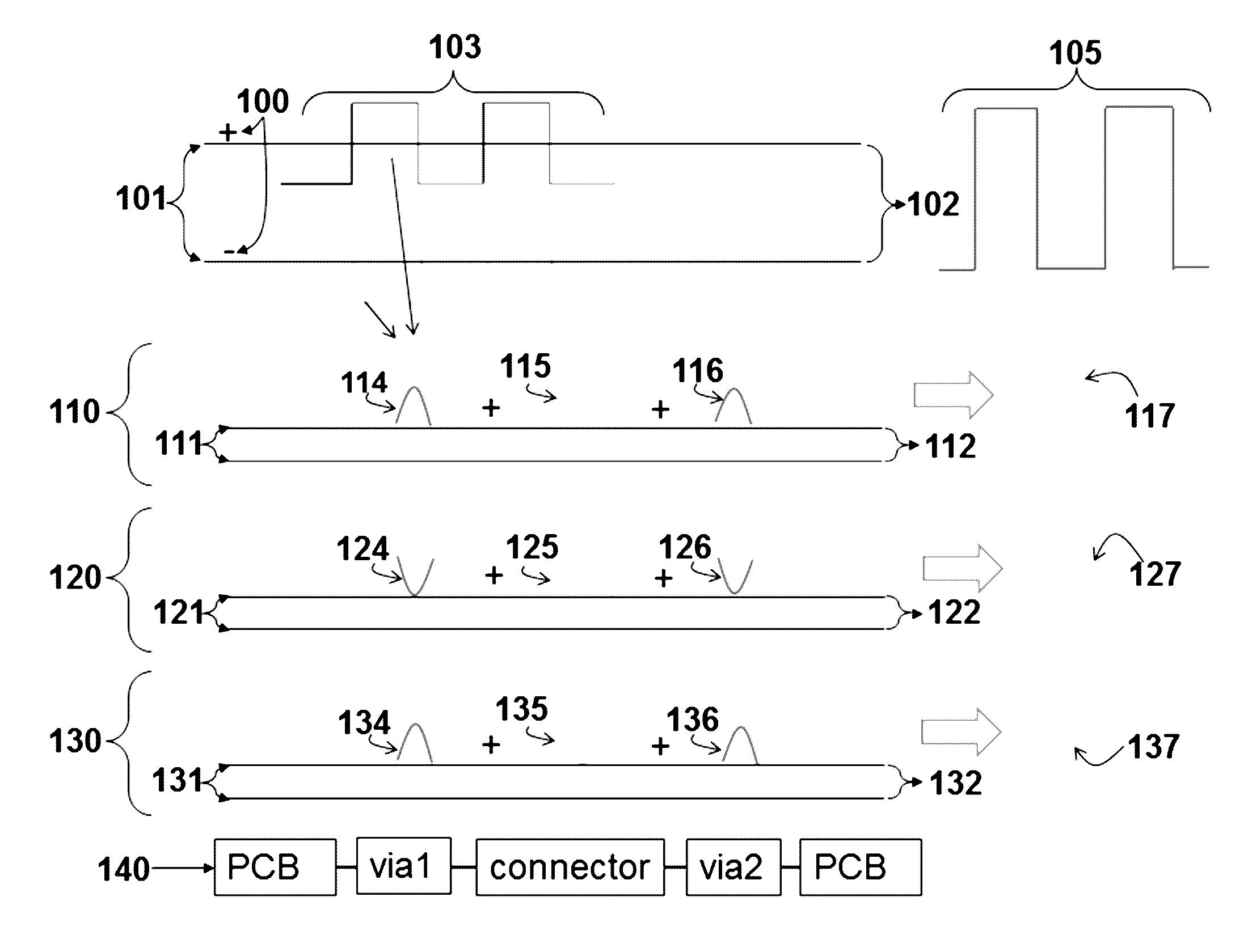
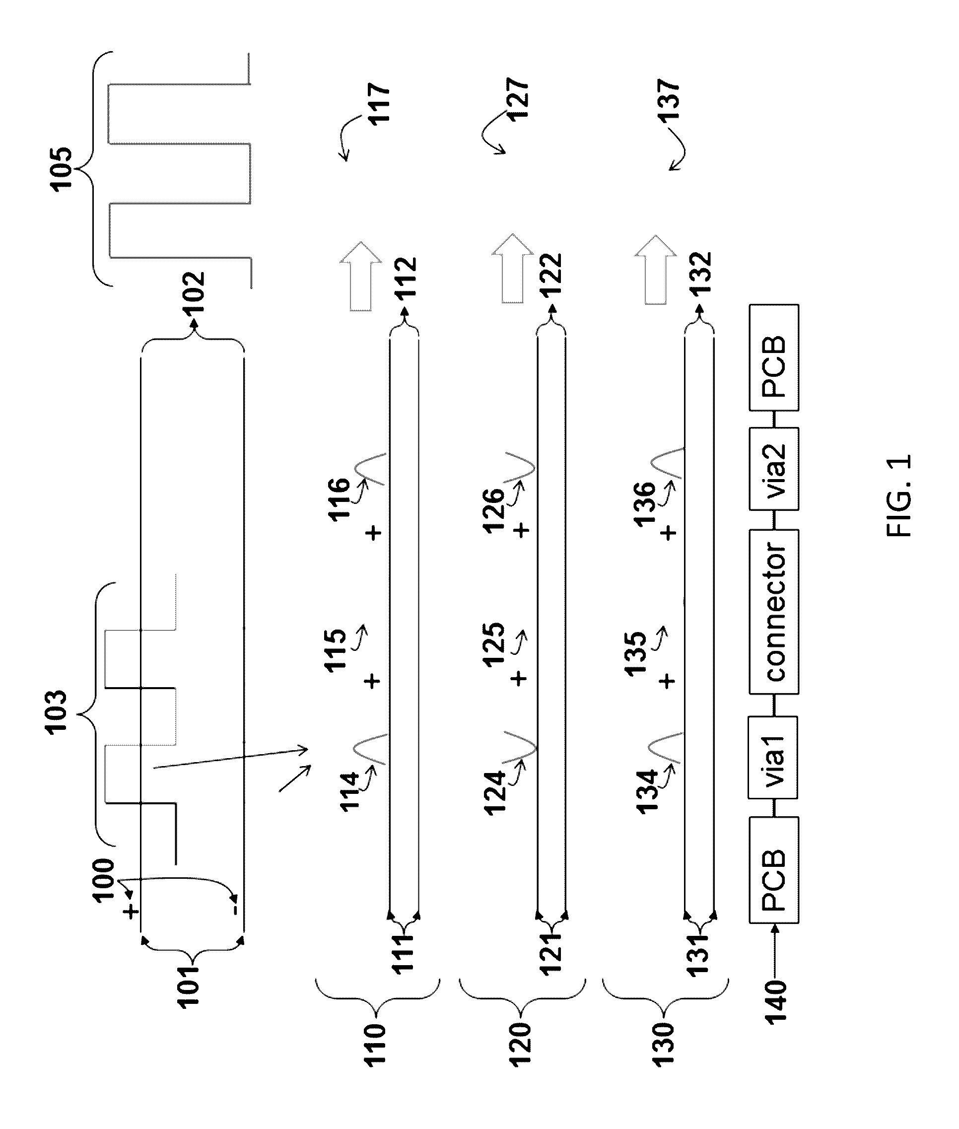
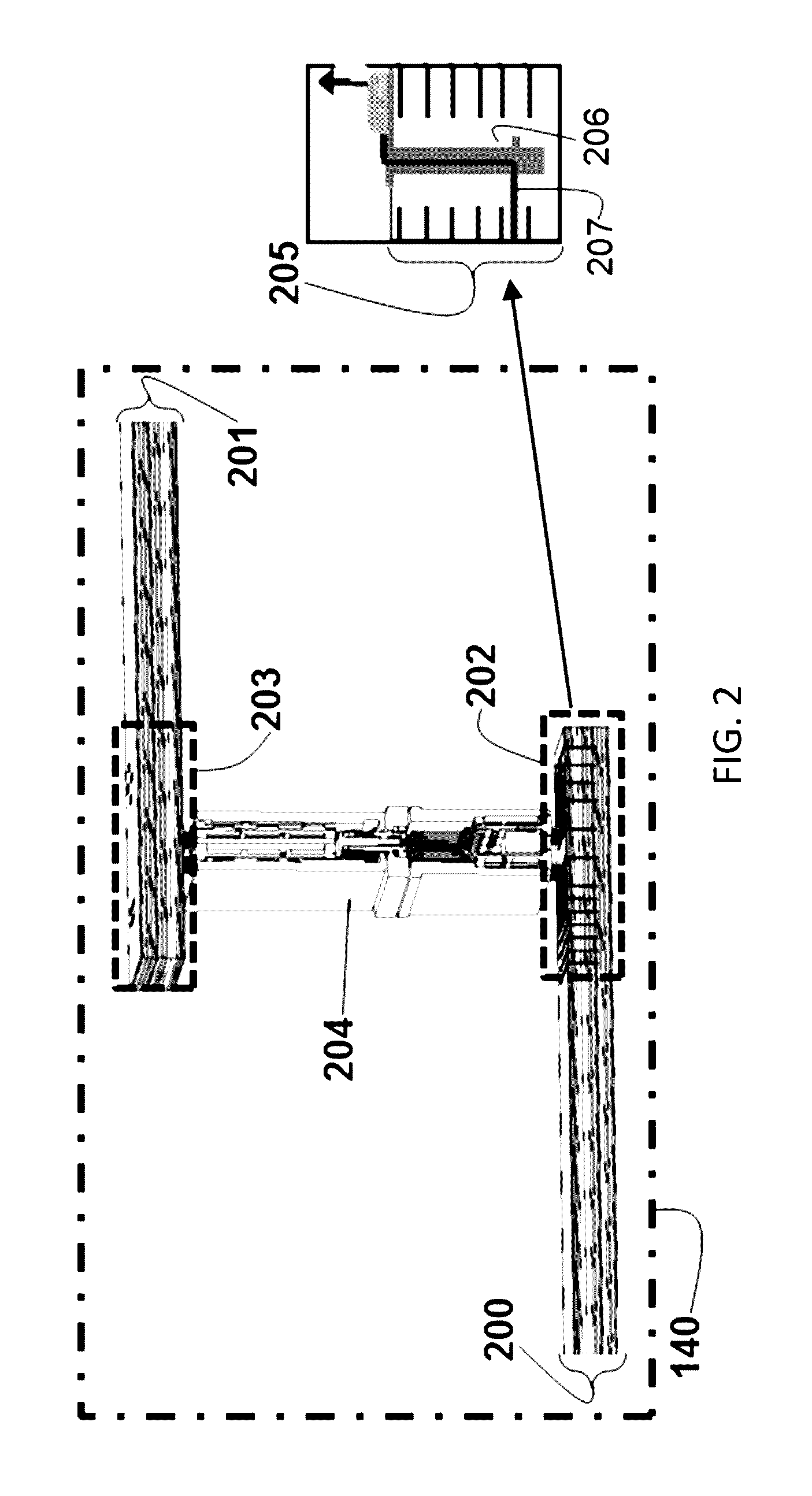
[0072 configuration 1950 of FIG. 19(c) illustrates an implementation within a connector by applying both edge-coupling 1955 and broadside coupling 1965 to signal conductors. Receptacle side 1956 and plug side 1957 are mated at 1954 as shown. Plug side 1957 signal conductors interface with cables 1953 at cable termination 1952. Insert molding 1962, of connector side view 1960 of FIG. 19(d), molds over connector conductors and connector shell 1967 encapsulates the mold. Differential FEXT from neighbor aggressors to a victim pair 1951 is expected to have small magnitude due to sequence of edge coupling 1955 and broadside coupling 1965 configurations. With optimum coupling length of each configuration, magnitude of both polarities will be similar and cumulative FEXT of the connector will be reduced.


PUM


Abstract

Systems, methods and apparatuses involving a chip-to-chip communication channel, for reducing Far End Crosstalk (FEXT) through the novel concept of controlling FEXT magnitude and polarity of a component inside a channel, vias or within a connector by implementing broadside and edge couplings to offset cumulative FEXT in a channel, via-connector-via subsystem or a connector. The example implementations described herein can be applied to a chip-to-chip communication channel, mezzanine connectors, backplane connectors and any other connectors requiring via routing, and connector itself that can benefit from FEXT reduction.

Description

CROSS REFERENCE TO RELATED APPLICATIONS[0001]This application claims priority to U.S. provisional patent application No. 62 / 009,801 filed on Jun. 9, 2014, which is incorporated herein by reference in its entirety for all purposes.BACKGROUND[0002]Field[0003]Systems, apparatuses, methods and example implementations described herein are generally directed to systems for reducing Far-End Crosstalk (FEXT) and, more particularly, to the reduction of FEXT in electrical connectors and plated through holes that are transmitting differential signals.[0004]Related Art[0005]As demand for higher bandwidth continues to grow in telecommunication industry, each device may require more computational power and routing capability. The data rate for each signal channel continues to increase, as does signal density. As a result, unwanted noise, or electromagnetic coupling occurring between neighbor channels significantly increases. For high-speed applicability and reduction in noise compared to single-e...

Claims


Application Information

Patent Timeline
Patent Type & Authority Patents(United States)
IPC IPC(8): H01R12/00H05K1/02H01R13/6469H05K1/11
CPCH05K1/0228H01R13/6469H05K1/115H05K1/0245
Inventor AIHARA, KUNIAHUANG, CHING-CHAO
Owner HIROSE ELECTRIC GROUP
Why Eureka
Try Eureka