Conveyor belt and belt constituent members

a technology of conveyor belts and constituent parts, which is applied in the direction of conveyors, transportation and packaging, etc., can solve the problems of ball unit detachment risk b>86

Active Publication Date: 2017-01-31
TSUBAKIMOTO CHAIN CO
View PDF46 Cites 10 Cited by
  • Summary
  • Abstract
  • Description
  • Claims
  • Application Information

AI Technical Summary

Benefits of technology

[0030]In this structure, one end or opposite ends of the belt component form the end portion of the conveyor belt in the width direction, thereby obtaining the same advantages as that of the conveyor belt.

Problems solved by technology

This further causes the risk of detachment of the ball unit 86 from the recess part 82a.

Method used


Image

  • Conveyor belt and belt constituent members
  • Conveyor belt and belt constituent members
  • Conveyor belt and belt constituent members

Examples


first embodiment

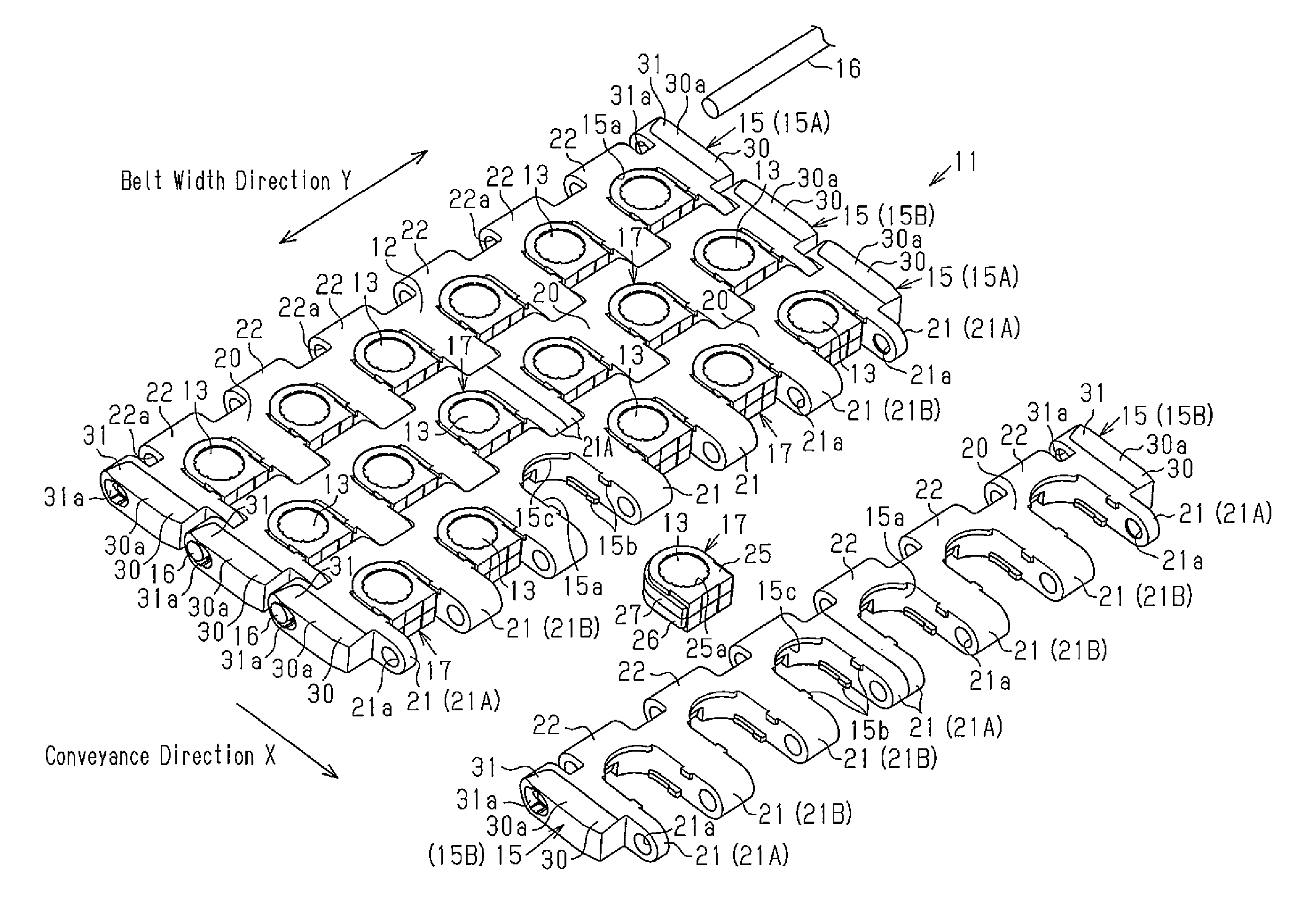
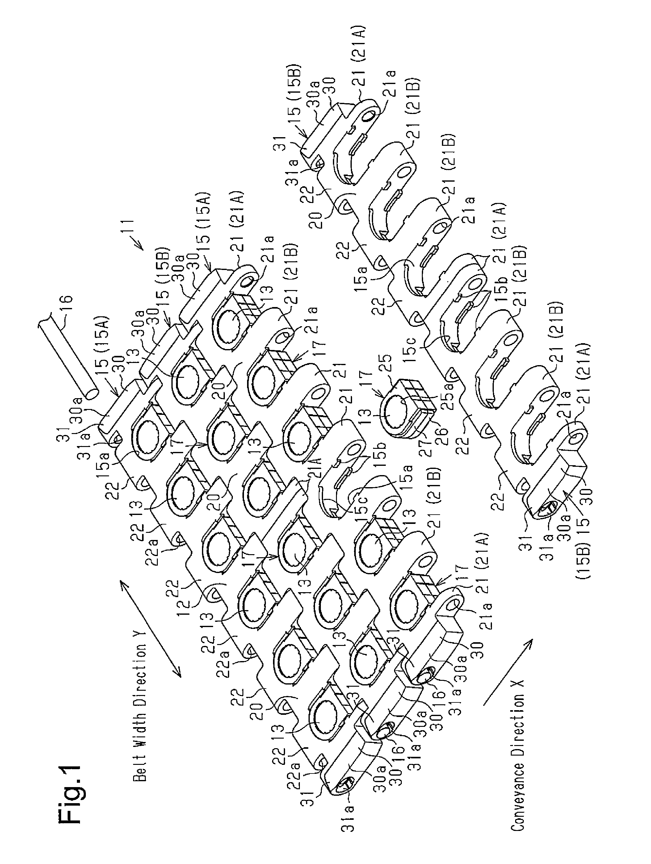
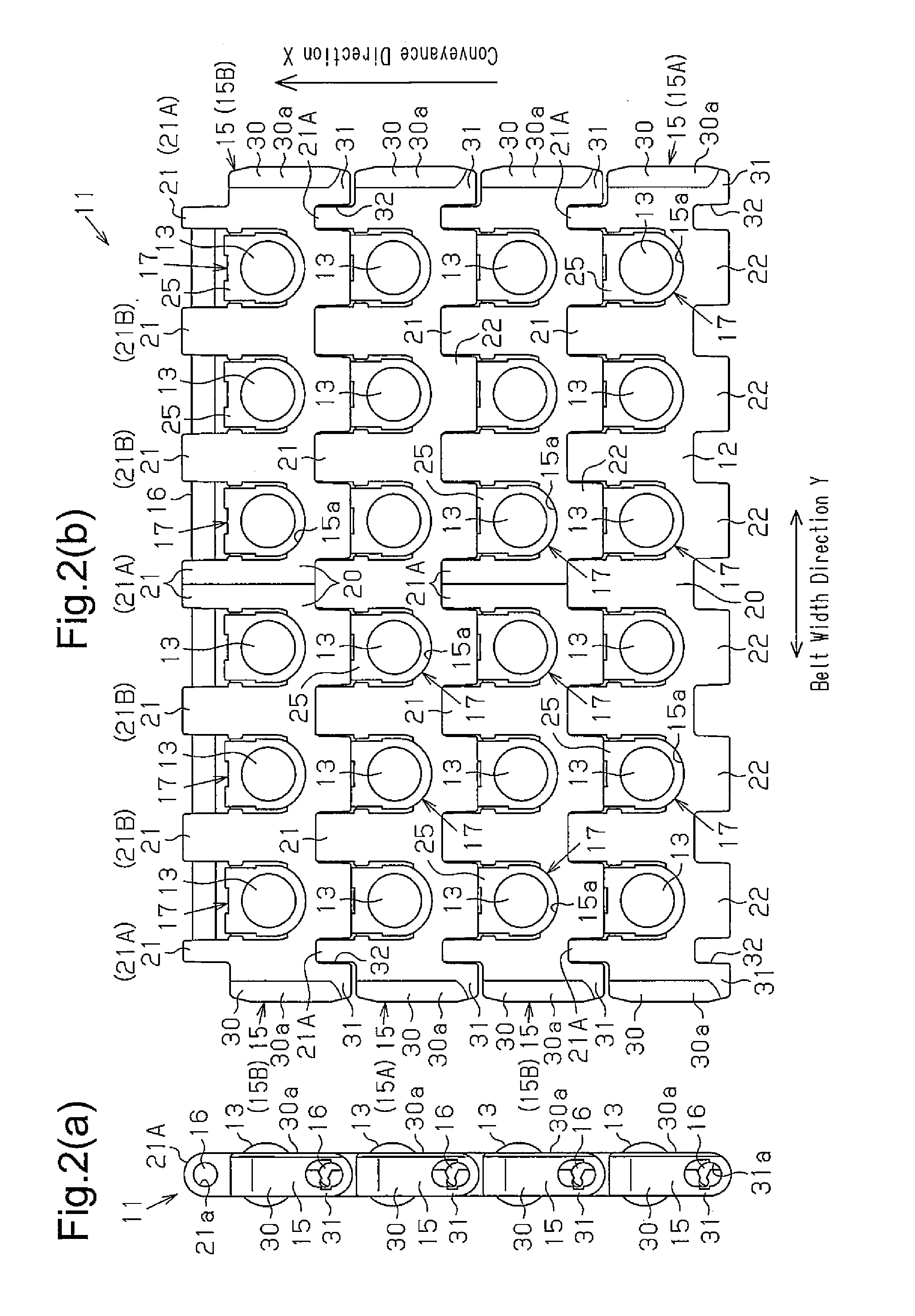
[0046]A first embodiment of this invention is described below based on FIGS. 1 to 3(b). In the first embodiment, a conveyor belt 11 of this invention is embodied in a conveyor belt with balls. In the following description of the conveyor belt 11, a direction in which an item is conveyed is called a conveyance direction X and a direction crossing the conveyance direction X is called a belt width direction Y. The longitudinal direction of the belt is parallel to the conveyance direction X. FIG. 1 shows only a part of the conveyor belt.

[0047]The conveyor belt 11 shown in FIG. 1 is configured as an endless belt with opposite ends (not shown in the drawings) of the conveyor belt 11 in the longitudinal direction of the belt coupled to each other. The conveyor belt 11 is wrapped around multiple sprockets (not shown in the drawings) while the opposite ends of the conveyor belt 11 in the longitudinal direction are in meshing engagement with the corresponding sprockets. When a motor as a powe...

second embodiment

[0076]A conveyor belt of a second embodiment is described next by referring to FIGS. 4(a) and 4(b).

[0077]In the first embodiment, the restricting part 31 protrudes in the same direction as the second hinge part 22. In the second embodiment, a restricting part 41 protrudes in the same direction as the first hinge part 21A.

[0078]As shown in FIGS. 4(a) and 4(b), a bulging part 40 is formed at an end portion of the conveyor belt 11 in the width direction. The bulging part 40 is formed at a lateral portion of the first hinge part 21A. The bulging part 40 is provided with a restricting part 41 protruding in the conveyance direction X. The restricting part 41 protrudes further than the tip of the first hinge part 21A toward a downstream side. The bulging part 40 is provided with a rectangular cutout 42 opened toward an upstream side. The cutout 42 receives the restricting part 41 of the chain link 15 adjacent to the bulging part 40. The bulging part 40 has an end surface 40b spaced by a sl...


PUM


Abstract

A conveyor belt (11) is formed by coupling multiple chain links 15 aligned in a conveyance direction X. The chain link (15) is provided with multiple recess parts (15a) and first hinge parts (21) protruding in the conveyance direction X from positions between which each of the recess parts (15a) is placed. If some object hits on an outer end of the conveyor belt (11) to apply force to the first hinge part (21), a section including the first hinge part (21) and a bulging part (30) pivots about a fulcrum at an outer base end of the first hinge part (21) to deform this section. In this invention, a point of action where force acts on the conveyor belt (11) and the center of pivotal motion of the first hinge part (21) and the bulging part (30) are determined to be spaced by a relatively short distance.

Description

TECHNICAL FIELD OF THE INVENTION[0001]This invention relates to a conveyor belt and belt constituent members.BACKGROUND OF THE INVENTION[0002]A conveyor belt is used in a belt conveying device to convey an item. A conveyor belt such as a modular belt disclosed in patent documents 1 to 5 includes multiple balls (free balls) arranged in a vertical direction and a horizontal direction. The multiple balls are attached to the conveyor belt while protruding from a surface of the belt.[0003]FIG. 7 shows an example of a conventional conveyor belt with balls. A conveyor belt 81 includes a belt part 84. The belt part 84 is formed of multiple chain links 82 each provided as an example of belt component. The multiple chain links 82 are aligned in the longitudinal direction of the belt parallel to a conveyance direction X. Each chain link 82 is arranged in a manner such that the longitudinal direction of the chain link 82 agrees with a width direction Y crossing the conveyance direction X. The b...

Claims


Application Information

Patent Timeline
Patent Type & Authority Patents(United States)
IPC IPC(8): B65G17/08B65G17/40B65G17/24
CPCB65G17/40B65G17/24
Inventor ISHIKAWA, MASAYUKIOZAKI, HAJIMESHIBAYAMA, KATSUTOSHI
Owner TSUBAKIMOTO CHAIN CO
Why Eureka
Try Eureka