
Metering apparatus for and method of determining a characteristic of a fluid flowing through a pipe

a technology of metering apparatus and fluid flow, which is applied in the direction of indirect mass flowmeters, instruments, measurement devices, etc., can solve the problems of reducing the efficiency of the flow circuit, meter producing false readings, disrupting and changing fluid flow characteristics, etc., and achieves the effect of easy determination of the bending force on the non-linear section

Inactive Publication Date: 2017-01-31
AIRBUS OPERATIONS LTD
View PDF16 Cites 2 Cited by
  • Summary
  • Abstract
  • Description
  • Claims
  • Application Information

AI Technical Summary

Benefits of technology

[0014]With this arrangement it is possible to determine the mass flow rate of the fluid flowing through the pipe without interrupting or interfering with the flow of fluid through the pipe.
[0015]It is possible to easily determine the bending force on the non-linear section of the pipe induced by the inertia of the fluid flowing through the pipe.
[0018]Therefore, it is possible to obtain dynamic readings of the volumetric flow rate of fluid flowing through the pipe based on a metering apparatus located external to the pipe.

Problems solved by technology

The presence of an obstruction or restriction in the flow path to obtain a pressure drop reduces the efficiency of the flow circuit.
Furthermore, the obstruction or restriction may trap contaminates, such as ice, and lead to the meter producing a false reading.
The obstruction or restriction may also disrupt and change the fluid flow characteristics.
However, this also requires an obstacle in the flow path.
Such an arrangement is also not suitable in some fluid systems, such as fuel systems.
However, an obstacle is present in the flow path.
Furthermore, the use of a heated ignition source is not acceptable for some fluid systems, such as fuel systems.
However, such an arrangement is not suitable for aircraft and requires moving parts.
However, such a metering arrangement is present in the fluid flow and has a significant step change in flow section as the fluid translates through the jet nozzle and so induces a significant pressure drop.

Method used


Image

  • Metering apparatus for and method of determining a characteristic of a fluid flowing through a pipe
  • Metering apparatus for and method of determining a characteristic of a fluid flowing through a pipe
  • Metering apparatus for and method of determining a characteristic of a fluid flowing through a pipe

Examples


Embodiment Construction

)

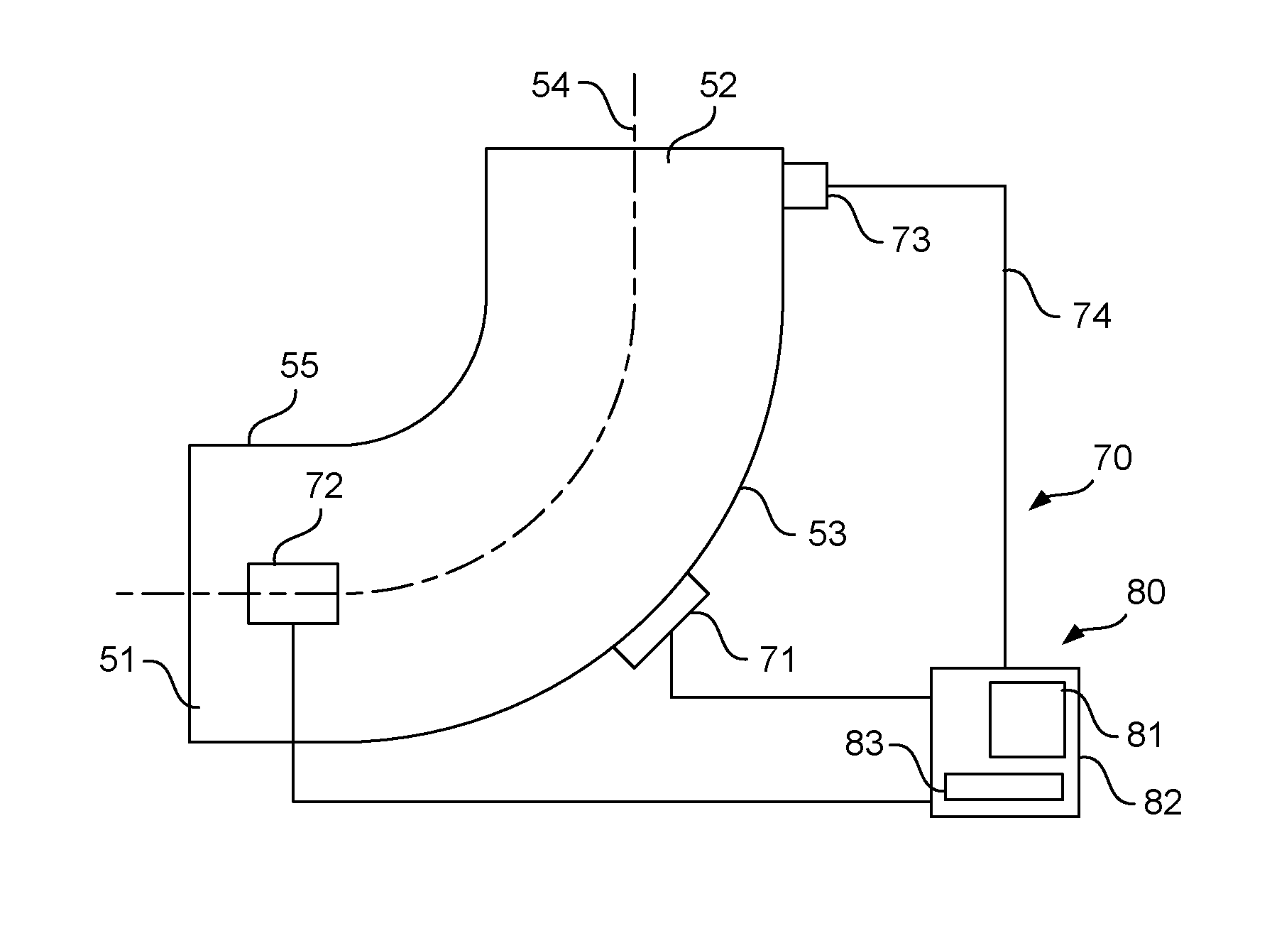
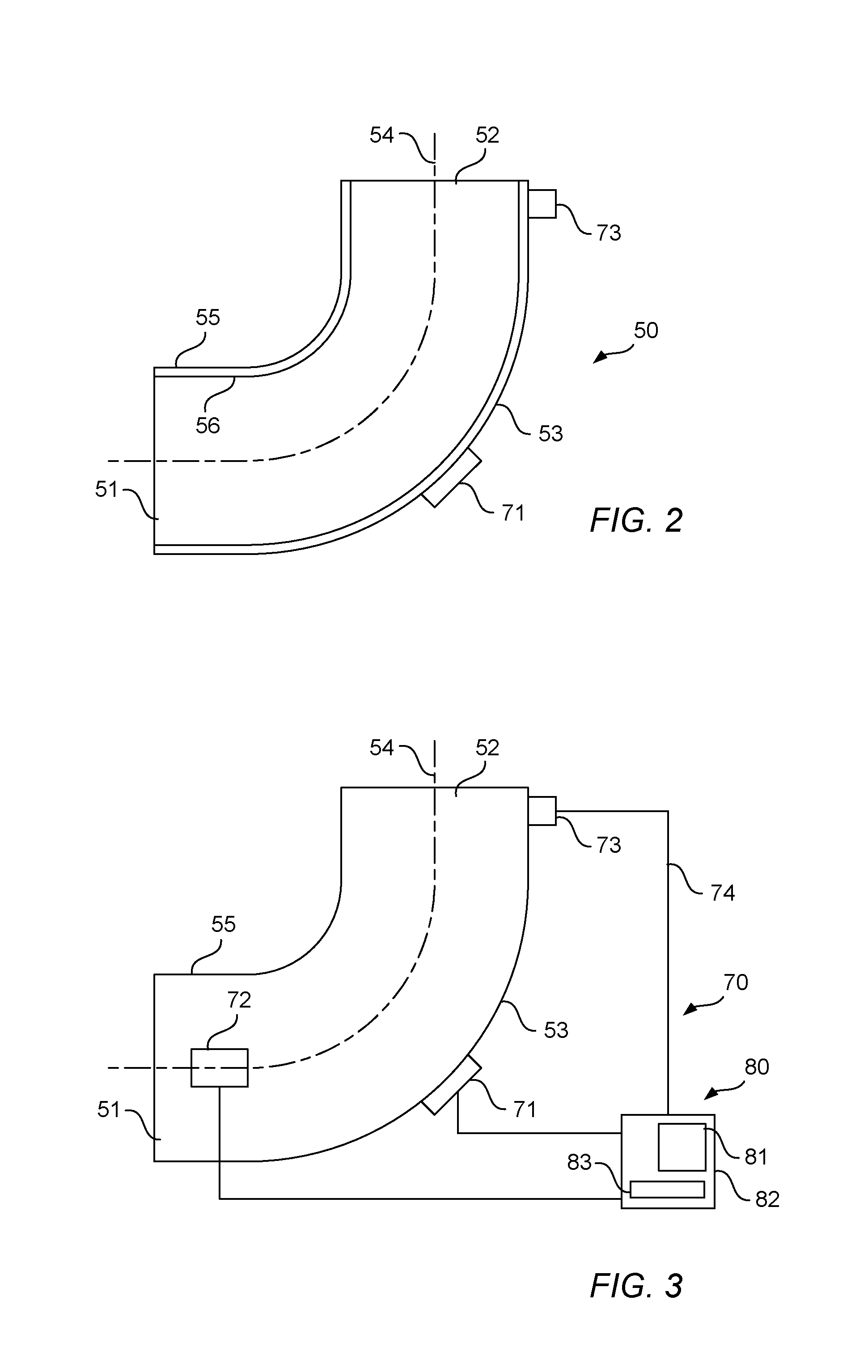
[0046]Part of an aircraft fuel system 40 is shown in FIG. 2 and FIG. 3. The part of the aircraft fuel system 40 includes a non-linear section of a pipe 50. Although in embodiments described herein the invention is described with reference to an aircraft fuel system, it will be understood that the invention may also be applicable to alternative fluid systems on an aircraft, for example a hydraulic system. Similarly, the invention may be applicable to a fluid system on other vehicular applications or non-vehicular systems.

[0047]The non-linear section of the pipe 50 has a first end 51 and a second end 52. The first end 51 acts as a fluid inlet or fluid outlet to the non-linear section of the pipe 50, dependent on the direction of fluid flow. The second end 52 acts as a fluid inlet or fluid outlet to the non-linear section of the pipe 50, dependent on the direction of fluid flow.

[0048]In the present embodiment, the non-linear section of the pipe 50 is shown with linear portions at the ...


PUM


Abstract

A metering apparatus for determining a characteristic of a fluid, such as the volumetric flow rate, flowing through a non-linear section of a pipe is disclosed having a first strain gauge mountable to the non-linear section of the pipe offset from the bending neutral axis of the non-linear section of the pipe, to detect a bending force on the non-linear section of the pipe induced by the inertia of the fluid flowing through the pipe. A second strain gauge is mountable to the pipe disposed on the bending neutral axis of the non-linear section of the pipe, to detect at least one of the hoop strains, longitudinal strains and radial strains imparted on the pipe by the pressure of the fluid flowing through the pipe. A controller is configured to determine the mass flow rate of fluid flowing through the pipe based on the bending force determined by the first strain gauge and the at least one of the hoop strains, longitudinal strains and radial strains determined by the second strain gauge.

Description

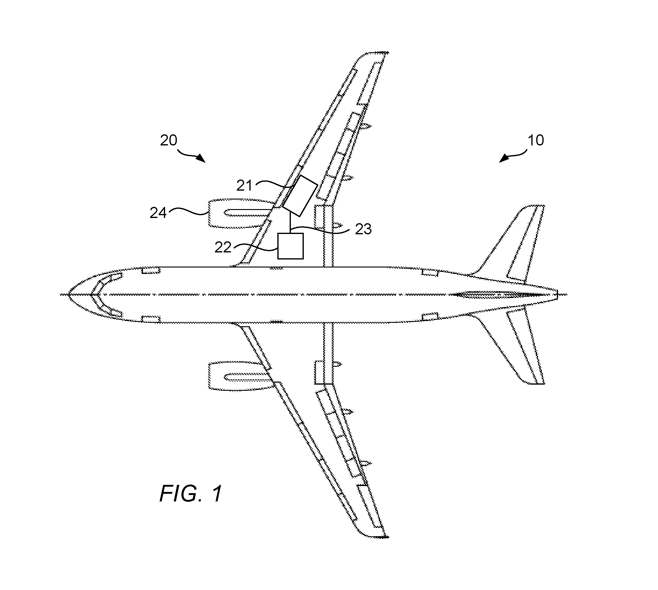
RELATED APPLICATIONS[0001]The present application claims priority from Great Britain Application Number 1509319.8, filed May 29, 2015, the disclosure of which is hereby incorporated by reference herein in its entirety.FIELD OF THE INVENTION[0002]The present invention relates to a metering apparatus for determining a characteristic of a fluid flowing through a non-linear section of a pipe. The present invention also relates to a method of determining a characteristic of a fluid flowing through a non-linear section of a pipe.BACKGROUND OF THE INVENTION[0003]An aircraft 10 is shown in FIG. 1. Such an aircraft has a number of fluid systems, including a fuel system 20. The fuel system 20 has fuel tanks 21, 22 and conduits 23 for transferring fuel around the aircraft. Conduits 23 supply fuel to the aircraft's engines 24. Conduits 23 also transfer fuel between fuel tanks 21, 22. Such fuel transfer between fuel tanks 21, 22 affects the weight distribution of the aircraft 10. Therefore, it i...

Claims


Application Information

Patent Timeline
Patent Type & Authority Patents(United States)
IPC IPC(8): G01F1/84G01F1/88
CPCG01F1/88G01F1/206G01F1/80
Inventor EDMOND, GEORGEWHITLOCK, RHONACASE, ROBERT
Owner AIRBUS OPERATIONS LTD
Learn More