Fastener assembly

a technology of fasteners and assembly parts, which is applied in the direction of fastening means, pins, screws, etc., can solve the problems of requiring extensive 100 man-hours for fastener installation alone in a typical 55-foot diameter radome, and the risk of loosening of nut-and-bolt fasteners, so as to achieve quick and reliable connection

Active Publication Date: 2017-02-07
INFINITE TECH RCS INC
View PDF13 Cites 16 Cited by
  • Summary
  • Abstract
  • Description
  • Claims
  • Application Information

AI Technical Summary

Benefits of technology

[0015]The fastener assembly thus advantageously provides for quick and reliable connection of the first and second panels. The unique configuration of the tee portion of the fastener pin allows the fastener pin to be installed by hand. Furthermore, the interconnection of the tee portion of the fastener pin and the seat of the insert, along with the compression member, provides a desired pre-load without the use of calibrated torqueing devices. Furthermore, there is no need to re-torque the fastener assembly over time to maintain the desired pre-load.

Problems solved by technology

Each fastener in a radome must be tightened to a specified torque value to ensure proper connection, and this requires extensive man-hours for fastener installation alone.
By some estimates, each fastener takes about a minute to install, leading to over 100 man-hours for fastener installation alone in a typical 55-foot diameter radome.
Nut-and-bolt fasteners are also likely to loosen over time, requiring even more man-hours in fastener inspection, along with the need for re-torqueing the fasteners over the life of the radome.
When maintenance is required, if the adhesive bond on the nut is broken, the fastener may merely spin in place rather than tighten.
In such a situation, depending on the configuration of the connection (e.g., the nut and bolt are on opposite sides of the radome panels), re-torqueing or removal of the fastener may require substantially more time, as simultaneous access to both portions of the fastener is not possible.

Method used


Image

  • Fastener assembly
  • Fastener assembly
  • Fastener assembly

Examples


Embodiment Construction

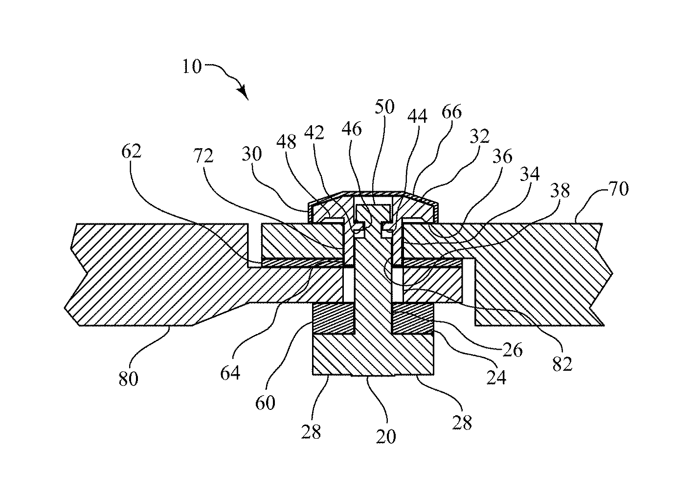
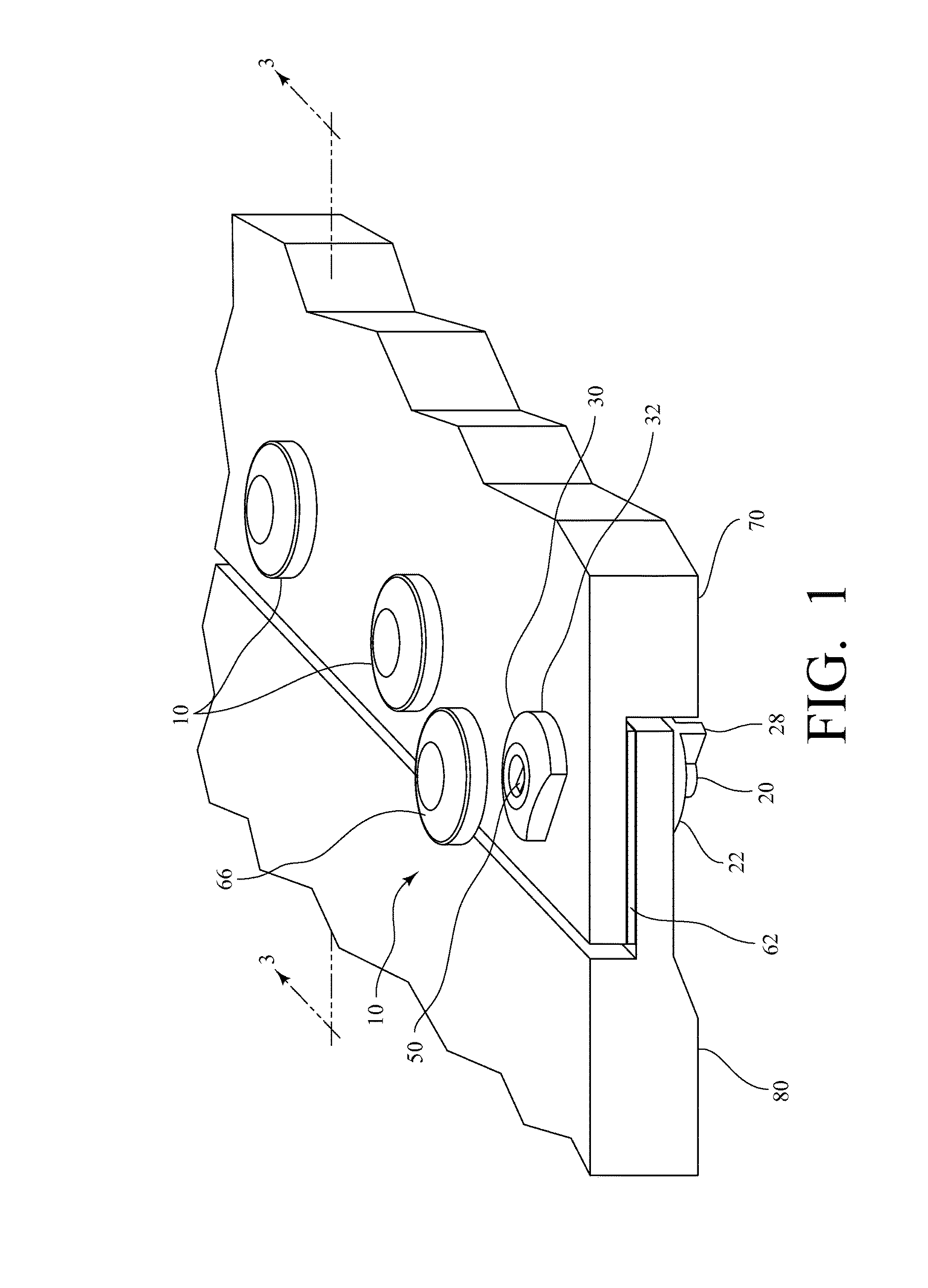
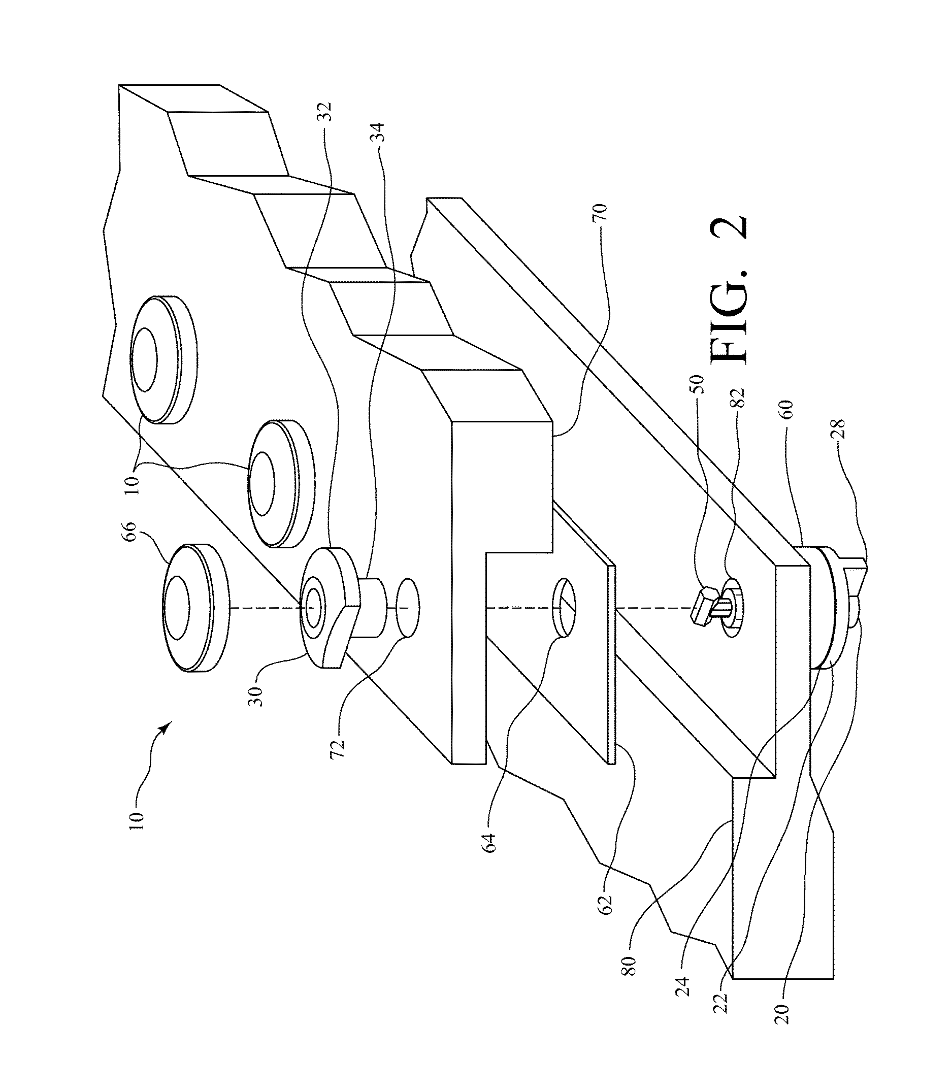
[0027]The present invention is a fastener assembly that has particular applicability and utility in the installation of radome panels.

[0028]As shown in FIGS. 1-6, an exemplary fastener assembly 10 made in accordance with the present invention comprises a fastener pin 20, an insert 30, and a compression member 60. In some embodiments, the fastener assembly 10 may also include a panel gasket 62 and a cap 66, as further described below.

[0029]Referring now to FIG. 8, in this exemplary embodiment, the fastener pin 20 is comprised of a base 22, a shaft 26 that extends from a top surface 24 of the base 22, and two wings 28 that extend from a lower surface of the base 22, as further described below. The shaft 26 of the fastener pin 20 terminates in a tee portion 50, the function of which will also be described below.

[0030]With respect to FIG. 8, the shaft 26 is described as including a tee portion 50 because there are two lateral extensions (or wings) at or near a distal end of the shaft 26...


PUM


Abstract

A fastener assembly includes an insert having a head and a sleeve extending from a bottom surface of the head, with the insert further defining an internal cavity. The head of the insert abuts a first panel with the sleeve extending through a first preformed hole in the first panel. A second panel with a second preformed hole is aligned with the first panel, and a shaft of a fastener pin is inserted through the second preformed hole and into the internal cavity of the insert. Upon rotating the fastener pin, a tee portion at the end of the shaft engages a seat positioned in the internal cavity of the insert. The fastener assembly also includes a compression member positioned around the shaft of the fastener pin that biases the tee portion of the fastener pin into engagement with the seat of the insert.

Description

CROSS-REFERENCE TO RELATED APPLICATIONS[0001]The present application claims priority to U.S. Provisional Patent Application Ser. No. 61 / 993,855 filed on May 15, 2014, the entire disclosure of which is incorporated herein by reference.STATEMENT REGARDING FEDERALLY SPONSORED RESEARCH OR DEVELOPMENT[0002]This invention was made with government support under Contract No. FA8222-12-C-0007 awarded by the United States Air Force. The government has certain rights in the invention.BACKGROUND OF THE INVENTION[0003]The present invention relates to a fastener assembly, a fastener assembly that has particular applicability and utility in the installation of radome panels.[0004]A radome is an enclosure designed to protect radar antennas from outside weather and debris. A typical ground-based radome is constructed of a multitude of panels formed into a spherical enclosure. Each of the panels is connected by a plurality of fasteners, such that a typical 55-foot diameter radome may have more than 6...

Claims


Application Information

Patent Timeline
Patent Type & Authority Patents(United States)
IPC IPC(8): F16B5/10F16B19/00F16B5/00
CPCF16B5/10F16B19/002F16B5/00F16B5/0056F16B5/0642F16B21/02
Inventor TALBOT, CASEY AARONGILL, ANDREW W.SPENCER, ROBERT BRIANTAYLOR, JOHN D.SPENCER, KEVIN A.
Owner INFINITE TECH RCS INC
Why Eureka
Try Eureka