Fan securing device and fan assembly having the same

a technology of a fan assembly and a securing device, which is applied in the direction of electrical equipment construction details, machines/engines, liquid fuel engines, etc., can solve the problems that the conventional fan securing device is only capable of securing, and the conventional fan securing device cannot be adjusted to match the cooling fan of different dimensions, so as to facilitate the installation of the same, reduce resonance effects, and be easy to assembled

Active Publication Date: 2017-02-07
WISTRON CORP
View PDF9 Cites 7 Cited by
  • Summary
  • Abstract
  • Description
  • Claims
  • Application Information

AI Technical Summary

Benefits of technology

[0008]Therefore, an object of the present disclosure is to provide a fan securing device that can be combined with a cooling fan into an assembly which is easy to be mounted to an electronic device, and that is adjustable for holding cooling fans having different thicknesses.
[0013]The effect of the present disclosure lies in that the fan assembly according to the present disclosure combines a cooling fan and a fan securing device into an assembly, which facilitates installation of the same onto a board. Further, the fan securing device and the cooling fan may be easily assembled without the use of bolts or other securing members. Also, shock absorbing members may be respectively disposed between the cooling fan and the first holder and between the cooling fan and the second holder so as to reduce a resonance effect due to vibration when the cooling fan is in operation. Moreover, the fan securing device is suitable for a variety of cooling fans having different thicknesses, thereby simplifying an overall manufacturing process and reducing an overall manufacturing cost required to accommodate different sized cooling fans. Furthermore, a plurality of the fan assemblies of the disclosure may be connected together as desired.

Problems solved by technology

However, a conventional fan securing device generally is only capable of securing cooling fans of the same dimensions.
In other words, the conventional fan securing device cannot be adjusted to match cooling fans of different dimensions.

Method used


Image

  • Fan securing device and fan assembly having the same
  • Fan securing device and fan assembly having the same
  • Fan securing device and fan assembly having the same

Examples


Embodiment Construction

[0031]Before the present disclosure is described in greater detail, it should be noted that like elements are denoted by the same reference numerals throughout the disclosure.

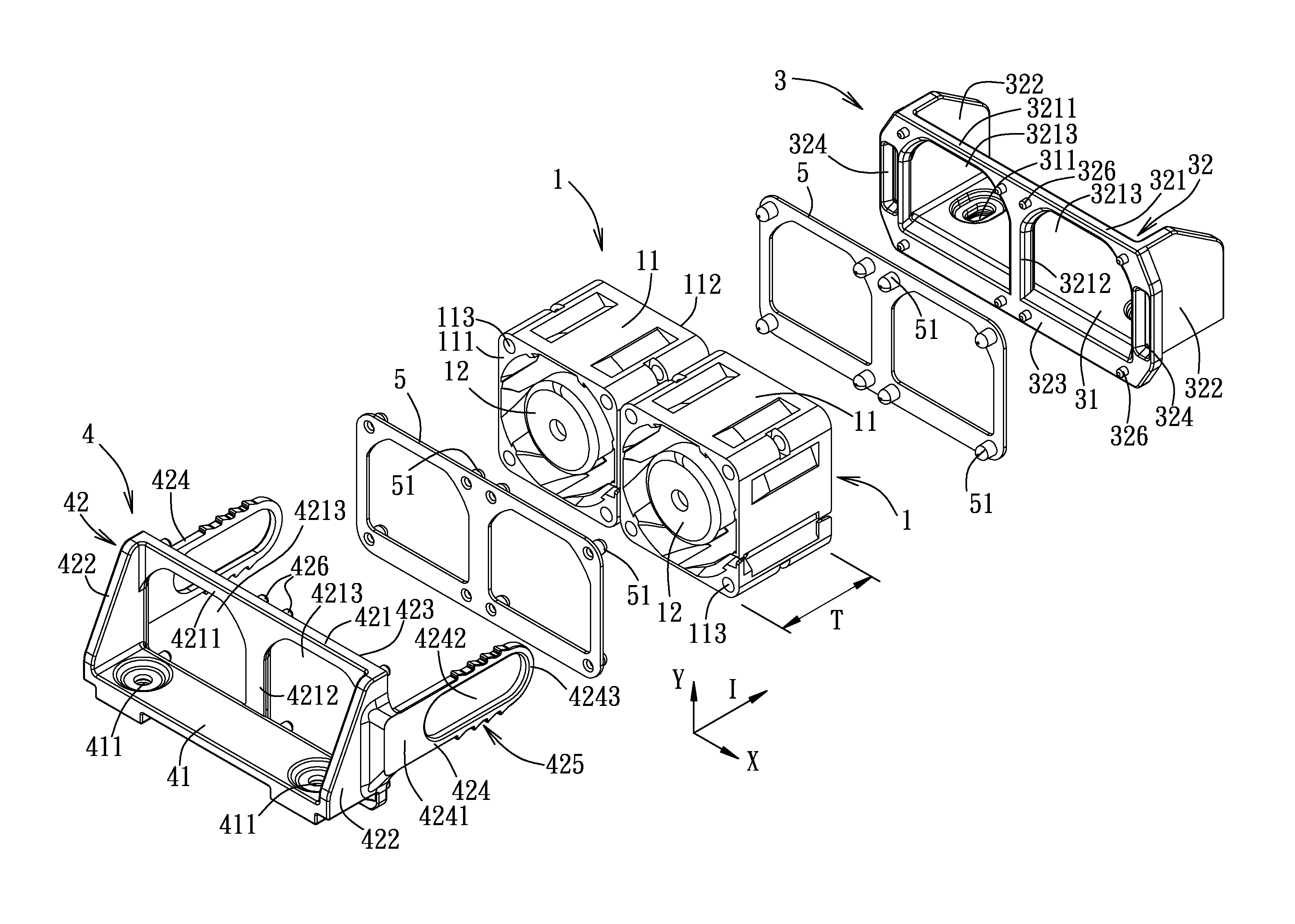
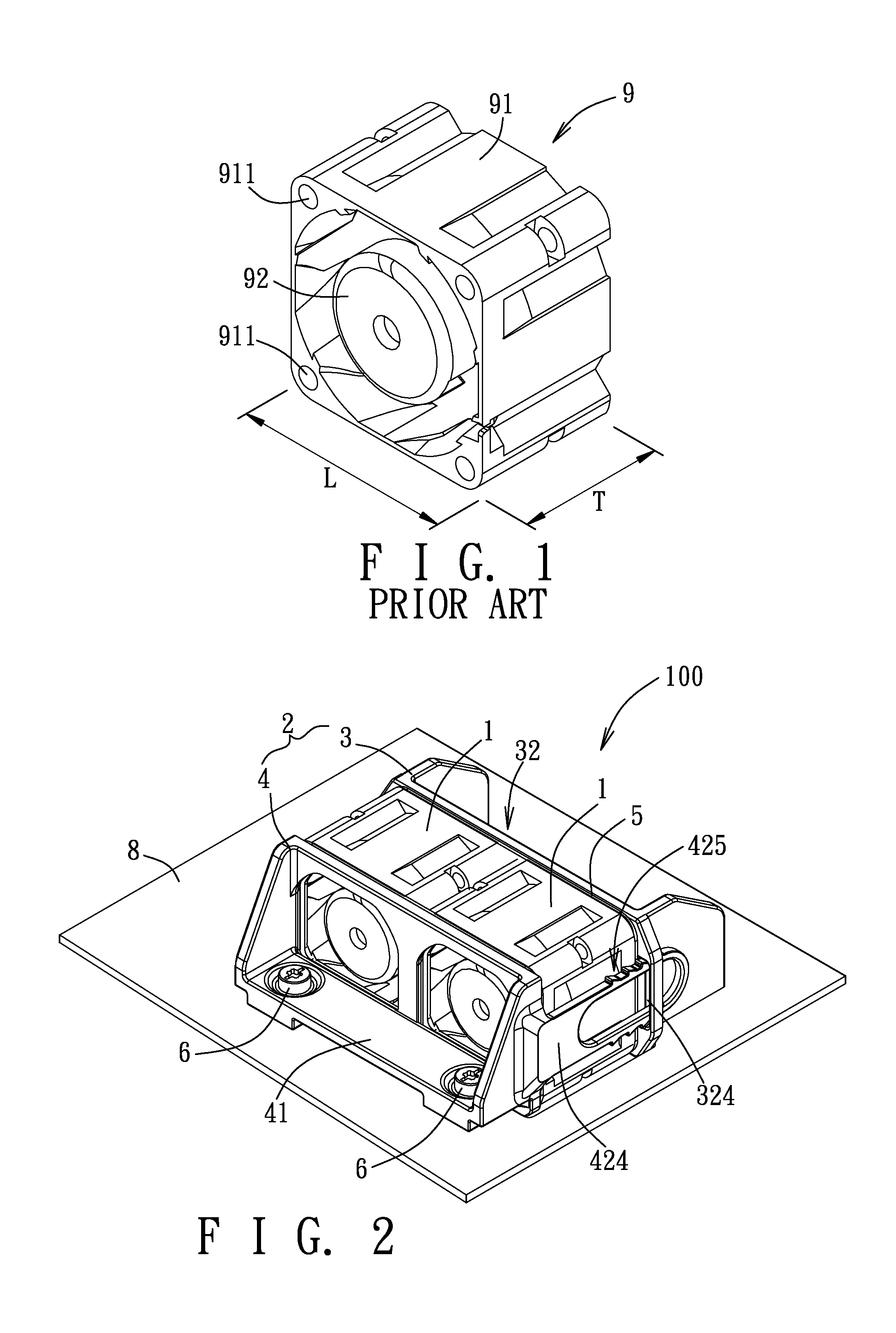
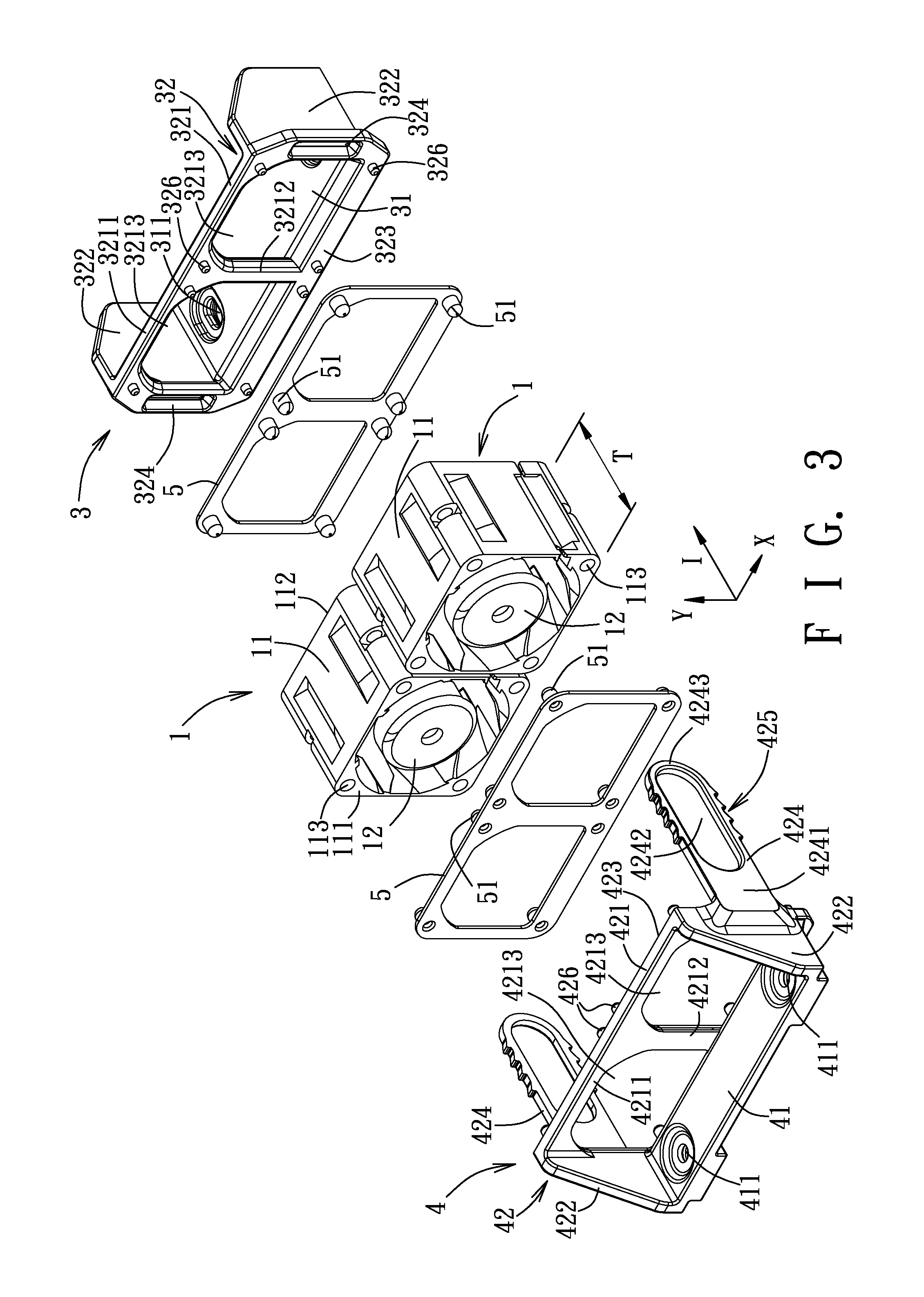
[0032]Referring to FIGS. 2 to 5, a first embodiment of a fan assembly 100 according to the present disclosure is adapted to be mounted on a board 8 such as a circuit board, and comprises two identical cooling fans 1 for an electronic device and a fan securing device 2.

[0033]Each of the cooling fans 1 includes a fan seat 11 with a square cross-section and a blade unit 12 (where no blade is shown in the figures). The fan seat 11 is hollow and has a front surface 111, a rear surface 112, and a plurality of positioning holes 113 extending through the front surface 111 and the rear surface 112 and respectively located at corners of the fan seat 11.

[0034]The fan securing device 2 includes a first holder 3, a second holder 4, and two hollow shock absorbing members 5. The second holder 4 is spaced apart from the first ...


PUM


Abstract

A fan securing device includes first and second holders. The first holder includes a first holding frame that has two holding slots located in opposite sides of the first holding frame, and two first locking units respectively formed adjacent to the holding slots. The second holder includes a second holding frame that has two connecting arms located on opposite sides of the second holding frame and extending respectively into the holding slots. Each connecting arm has a plurality of second locking units. Each first locking unit engages a selected one of the second locking units of a respective one of the connecting arms so as to clamp at least one cooling fan between the first and second surfaces.

Description

CROSS-REFERENCE TO RELATED APPLICATION[0001]This application claims priority of Taiwan Patent Application No. 102106263, filed on Feb. 22, 2013, the entire disclosure of which is incorporated herein by reference.BACKGROUND OF THE DISCLOSURE[0002]1. Field of the Disclosure[0003]The disclosure relates to a fan securing device, more particularly to a fan securing device adjustable for holding cooling fans having different thicknesses, and to a fan assembly having the fan securing device.[0004]2. Description of the Related Art[0005]Referring to FIG. 1, a cooling fan 9 for an electronic device generally comprises a fan seat 91 with a square cross-section, and a blade unit 92 that is received rotatably in the fan seat 91. The fan seat 91 has a plurality of positioning holes 911 extending therethrough and respectively located at four corners thereof. The positioning holes 911 allow securing members (not shown) such as bolts to extend respectively therethrough so as to secure the cooling fa...

Claims


Application Information

Patent Timeline
Patent Type & Authority Patents(United States)
IPC IPC(8): F04D29/52H05K7/20
CPCH05K7/20172F04D25/08F04D29/522
Inventor TSAI, CHI-KEN
Owner WISTRON CORP
Why Eureka
Try Eureka